Nissan Maxima Service and Repair Manual: P0455 evap control system
DTC Logic
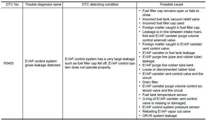
DTC DETECTION LOGIC
This diagnosis detects a very large leakage (fuel filler cap fell off etc.) in EVAP system between the fuel tank and EVAP canister purge volume control solenoid valve.
CAUTION:
- Use only a genuine NISSAN fuel filler cap as a replacement. If an incorrect fuel filler cap is used, the MIL may illuminate.
- If the fuel filler cap is not tightened properly, the MIL may illuminate.
- Use only a genuine NISSAN rubber tube as a replacement.
DTC CONFIRMATION PROCEDURE
1.PRECONDITIONING
CAUTION: Never remove fuel filler cap during the DTC Confirmation Procedure.
If DTC Confirmation Procedure has been previously conducted, always perform the following before conducting the next test.
- Turn ignition switch OFF and wait at least 10 seconds.
- Turn ignition switch ON.
- Turn ignition switch OFF and wait at least 10 seconds.
Check that EVAP hoses are connected to EVAP canister purge volume control solenoid valve properly.
TESTING CONDITION:
- Perform "DTC WORK SUPPORT" when the fuel level is between 1/4 and 3/4 full, and vehicle is placed on flat level surface.
- Open engine hood before conducting the following procedures.
2.PERFORM DTC CONFIRMATION PROCEDURE
With CONSULT
- Tighten fuel filler cap securely until ratcheting sound is heard.
- Turn ignition switch ON.
- Turn ignition switch OFF and wait at least 10 seconds.
- Turn ignition switch ON and select "DATA MONITOR" mode with CONSULT.
- Check that the following conditions are met.
COOLAN TEMP/S: 0 - 70C (32 - 158F) INT/A TEMP SE: 0 - 60C (32 - 140F)
- Select "EVP V/S LEAK P0456/P1456" of "EVAPORATIVE SYSTEM" in "DTC
WORK SUPPORT" mode
with CONSULT.
Follow the instructions displayed.
NOTE: If the engine speed cannot be maintained within the range displayed on the CONSULT screen
3.CHECK DTC
Check DTC.
4.PERFORM DTC CONFIRMATION PROCEDURE
With GST
NOTE: Be sure to read the explanation of EC-26, "SRT Set Driving Pattern" before driving vehicle.
- Start engine.
- Drive vehicle according to EC-26, "SRT Set Driving Pattern".
- Stop vehicle.
- Turn ignition switch OFF and wait at least 10 seconds.
- Turn ignition switch ON.
- Turn ignition switch OFF and wait at least 10 seconds.
- Turn ignition switch ON.
- Check 1st trip DTC.
Diagnosis Procedure
1.CHECK FUEL FILLER CAP DESIGN
- Turn ignition switch OFF.
- Check for genuine NISSAN fuel filler cap design.
2.CHECK FUEL FILLER CAP INSTALLATION
Check that the cap is tightened properly by rotating the cap clockwise.
3.CHECK FUEL FILLER CAP FUNCTION
Check for air releasing sound while opening the fuel filler cap.
4.CHECK FUEL TANK VACUUM RELIEF VALVE
5.CHECK EVAP PURGE LINE
Check EVAP purge line (pipe, rubber tube, fuel tank and EVAP canister) for cracks, improper connection or disconnection.
6.CLEAN EVAP PURGE LINE
Clean EVAP purge line (pipe and rubber tube) using air blower.
7.CHECK DRAIN FILTER
8.CHECK EVAP CANISTER VENT CONTROL VALVE
Check the following.
- EVAP canister vent control valve is installed properly.
- EVAP canister vent control valve.
9.CHECK FOR EVAP LEAKAGE
10.CHECK EVAP CANISTER PURGE VOLUME CONTROL SOLENOID VALVE OPERATION
With CONSULT
- Disconnect vacuum hose from EVAP canister purge volume control solenoid valve at EVAP service port.
- Start engine.
- Perform "PURG VOL CONT/V" in "ACTIVE TEST" mode.
- Touch "Qu" on CONSULT screen to increase "PURG VOL CONT/V" opening to 100%.
- Check vacuum hose for vacuum.
Vacuum should exist.
11.CHECK EVAP CANISTER PURGE VOLUME CONTROL SOLENOID VALVE OPERATION
Without CONSULT
- Start engine and warm it up to normal operating temperature.
- Stop engine.
- Disconnect vacuum hose from EVAP canister purge volume control solenoid valve at EVAP service port.
- Start engine and let it idle for at least 80 seconds.
- Check vacuum hose for vacuum when revving engine up to 2,000 rpm.
Vacuum should exist.
12.CHECK VACUUM HOSE
Check vacuum hoses for clogging or disconnection
13.CHECK EVAP CANISTER PURGE VOLUME CONTROL SOLENOID VALVE
With CONSULT
- Start engine.
- Perform "PURG VOL CONT/V" in "ACTIVE TEST" mode with CONSULT. Check that engine speed varies according to the valve opening.
14.CHECK EVAP CANISTER PURGE VOLUME CONTROL SOLENOID VALVE
15.CHECK FUEL TANK TEMPERATURE SENSOR
16.CHECK EVAP CONTROL SYSTEM PRESSURE SENSOR
17.CHECK EVAP/ORVR LINE
Check EVAP/ORVR line between EVAP canister and fuel tank for clogging, kinks, looseness and improper connection.
18.CHECK RECIRCULATION LINE
Check recirculation line between filler neck tube and fuel tank for clogging, kinks, cracks, looseness and improper connection.
19.CHECK REFUELING EVAP VAPOR CUT VALVE
20.CHECK INTERMITTENT INCIDENT
Component Inspection
FUEL TANK VACUUM RELIEF VALVE (BUILT INTO FUEL FILLER CAP)
1.CHECK FUEL FILLER CAP
- Turn ignition switch OFF.
- Remove fuel filler cap.
- Wipe clean valve housing.
- Install fuel filler cap adapter (commercial service tool) to fuel filler cap.
- Check valve opening pressure and vacuum.
Pressure: 15.3 - 20.0 kPa (0.156 - 0.204 kg/cm2, 2.22 -
2.90 psi)
Vacuum: −6.0 to −3.3 kPa (−0.061 to −0.034 kg/cm2,
−0.87 to −0.48 psi)
2.REPLACE FUEL FILLER CAP
Replace fuel filler cap.
CAUTION: Use only a genuine fuel filler cap as a replacement. If an incorrect fuel filler cap is used, the MIL may illuminate.
DRAIN FILTER
- Check visually for insect nests in the drain filter air inlet.
- Check visually for cracks or flaws in the appearance.
- Check visually for cracks or flaws in the hose.
- Blow air into port A and check that it flows freely out of port B.
- Block port B.
- Blow air into port A and check that there is no leakage.
- If NG, replace drain filter.
 P0453 evap control system pressure sensor
Description
The EVAP control system pressure sensor detects pressure in the
purge line. The sensor output voltage to the ECM increases as pressure
increases.
DTC Logic
DTC DETECTION LOGIC
...
 P0456 evap control system
DTC Logic
DTC DETECTION LOGIC
NOTE:
If DTC P0456 is displayed with DTC P0442, first perform the trouble diagnosis
for DTC P0456.
This diagnosis detects very small leakage in the EVAP line betwe ...
Other materials:
Intelligent key system
Wiring Diagram
...
B2113 reclining motor
Description
The seat reclining motor is installed to the seatback assembly.
The seat reclining motor is activated with the driver seat control unit.
Tilts the seatback forward/backward by changing the rotation direction
of reclining motor.
DTC Logic
DTC DETECTION LOGIC
DTC No. ...
Heated seat
Wiring Diagram
...
Nissan Maxima Owners Manual
- Illustrated table of contents
- Safety-Seats, seat belts and supplemental restraint system
- Instruments and controls
- Pre-driving checks and adjustments
- Monitor, climate, audio, phone and voice recognition systems
- Starting and driving
- In case of emergency
- Appearance and care
- Do-it-yourself
- Maintenance and schedules
- Technical and consumer information
Nissan Maxima Service and Repair Manual

0.0055