
Nissan Maxima Service and Repair Manual: P0456 evap control system
DTC Logic
DTC DETECTION LOGIC
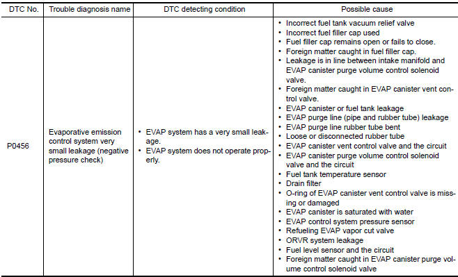
NOTE: If DTC P0456 is displayed with DTC P0442, first perform the trouble diagnosis for DTC P0456.
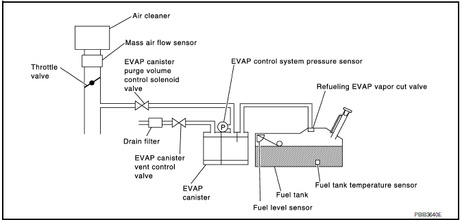
This diagnosis detects very small leakage in the EVAP line between fuel tank and EVAP canister purge volume control solenoid valve, using the intake manifold vacuum in the same way as conventional EVAP small leakage diagnosis.
If ECM judges a leakage which corresponds to a very small leakage, the very small leakage P0456 will be detected.
If ECM judges a leakage equivalent to a small leakage, EVAP small leakage P0442 will be detected.
If ECM judges that there are no leakage, the diagnosis will be OK.
CAUTION:
- Use only a genuine NISSAN fuel filler cap as a replacement. If an incorrect fuel filler cap is used, the MIL may illuminate.
- If the fuel filler cap is not tightened properly, the MIL may illuminate.
- Use only a genuine NISSAN rubber tube as a replacement.
DTC CONFIRMATION PROCEDURE
1.PRECONDITIONING
If DTC Confirmation Procedure has been previously conducted, always perform the following before conducting the next test.
- Turn ignition switch OFF and wait at least 10 seconds.
- Turn ignition switch ON.
- Turn ignition switch OFF and wait at least 10 seconds.
2.PRECONDITIONING
If DTC CONFIRMATION PROCEDURE has been previously conducted, always turn ignition switch OFF and wait at least 10 seconds before conducting the next test.
NOTE:
- After repair, make sure that the hoses and clips are installed properly.
- Check that EVAP hoses are connected to EVAP canister purge volume control solenoid valve properly.
TESTING CONDITION:
- Open engine hood before conducting the following procedure.
- If any of following conditions are met just before the DTC CONFIRMATION PROCEDURE, leave the vehicle for more than 1 hour.
- Fuel filler cap is removed.
- Fuel is refilled or drained.
- EVAP component part/parts is/are removed.
- Before performing the following procedure, confirm that battery voltage is more than 11 V at idle.
3.PERFORM DTC CONFIRMATION PROCEDURE
With CONSULT
- Turn ignition switch ON and select "DATA MONITOR" mode with CONSULT.
- Make sure the following conditions are met.
FUEL LEVEL SE: 0.25 - 1.4 V COOLAN TEMP/S: 0 - 32C (32 - 90F) FUEL T/TMP SE: 0 - 35C (32 - 95F) INT A/TEMP SE: More than 0C (32F) If NG, turn ignition switch OFF and leave the vehicle in a cool place (soak the vehicle), or refill/drain fuel until the output voltage of the "FUEL LEVEL SE" meets within the range above and leave the vehicle for more than 1 hour. Then start from step 1.
- Turn ignition switch OFF and wait at least 10 seconds.
- Turn ignition switch ON.
- Select "EVP V/S LEAKAGE P0456/P1456" of "EVAPORATIVE SYSTEM" in
"DTC WORK SUPPORT"
mode with CONSULT.
Follow the instructions displayed.
NOTE: If the engine speed cannot be maintained within the range displayed on CONSULT screen
4.PERFORM COMPONENT FUNCTION CHECK
Perform Component Function Check.
NOTE: Use Component Function Check to check the overall function of the EVAP very small leakage function. During this check, a 1st trip DTC might not be confirmed.
Component Function Check
1.PERFORM COMPONENT FUNCTION CHECK
With GST
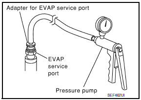
CAUTION:
- Never use compressed air, doing so may damage the EVAP system.
- Never start engine.
- Never exceeded 4.12 kPa (0.042 kg/cm2, 0.6 psi).
- Attach the EVAP service port adapter (commercial service tool) securely to the EVAP service port.
- Set the pressure pump and a hose.
- Also set a vacuum gauge via the 3-way connector and a hose.
- Turn ignition switch ON.
- Connect GST and select Service $08.
- Using Service $08 control the EVAP canister vent control valve (close).
- Apply pressure and make sure the following conditions are satisfied.
Pressure to be applied: 2.7 kPa (0.028 kg/cm2, 0.39 psi) Time to be waited after the pressure drawn in to the EVAP system and the pressure to be dropped: 60 seconds and the pressure should not be dropped more than 0.4 kPa (0.004 kg/cm2, 0.06 psi).
2.RELEASE PRESSURE
- Disconnect GST.
- Start engine and warm it up to normal operating temperature.
- Turn ignition switch OFF and wait at least 10 seconds.
- Restart engine and let it idle for 90 seconds.
- Keep engine speed at 2,000 rpm for 30 seconds.
- Turn ignition switch OFF.
NOTE: For more information, refer to GST Instruction Manual.
Diagnosis Procedure
1.CHECK FUEL FILLER CAP DESIGN
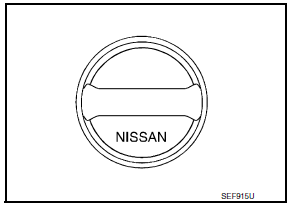
- Turn ignition switch OFF.
- Check for genuine NISSAN fuel filler cap design.
2.CHECK FUEL FILLER CAP INSTALLATION
Check that the cap is tightened properly by rotating the cap clockwise.
3.CHECK FUEL FILLER CAP FUNCTION
Check for air releasing sound while opening the fuel filler cap.
4.CHECK FUEL TANK VACUUM RELIEF VALVE
5.CHECK FOR EVAP LEAKAGE
6.CHECK DRAIN FILTER
7.CHECK EVAP CANISTER VENT CONTROL VALVE
Check the following.
- EVAP canister vent control valve is installed properly.
- EVAP canister vent control valve.
8.CHECK IF EVAP CANISTER IS SATURATED WITH WATER
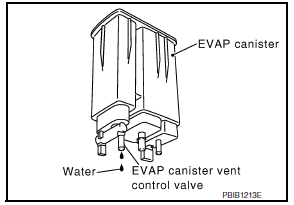
Remove EVAP canister with EVAP canister vent control valve and EVAP control system pressure sensor attached.
9.CHECK EVAP CANISTER
Weigh the EVAP canister with the EVAP canister vent control valve and EVAP control system pressure sensor attached.
The weight should be less than 2.1 kg (4.6 lb).
10.DETECT MALFUNCTIONING PART
Check the following.
- EVAP canister for damage
- EVAP hose between EVAP canister and drain filter for clogging or poor connection
11.CHECK EVAP CANISTER PURGE VOLUME CONTROL SOLENOID VALVE OPERATION
With CONSULT
- Disconnect vacuum hose connected to EVAP service port and EVAP canister purge volume control solenoid valve from EVAP canister purge volume control solenoid valve.
- Start engine.
- Perform "PURG VOL CONT/V" in "ACTIVE TEST" mode.
- Touch "Qu" on CONSULT screen to increase "PURG VOL CONT/V" opening to 100%.
- Check vacuum hose for vacuum.
Vacuum should exist.
12.CHECK EVAP CANISTER PURGE VOLUME CONTROL SOLENOID VALVE OPERATION
Without CONSULT
- Start engine and warm it up to normal operating temperature.
- Stop engine.
- Disconnect vacuum hose connected to EVAP service port and EVAP canister purge volume control solenoid valve from EVAP canister purge volume control solenoid valve.
- Start engine and let it idle for at least 80 seconds.
- Check vacuum hose for vacuum when revving engine up to 2,000 rpm.
Vacuum should exist.
13.CHECK VACUUM HOSE
Check vacuum hoses for clogging or disconnection.
14.CHECK EVAP CANISTER PURGE VOLUME CONTROL SOLENOID VALVE
15.CHECK FUEL TANK TEMPERATURE SENSOR
16.CHECK EVAP CONTROL SYSTEM PRESSURE SENSOR
17.CHECK EVAP PURGE LINE
Check EVAP purge line (pipe, rubber tube, fuel tank and EVAP canister) for cracks or improper connection.
18.CLEAN EVAP PURGE LINE
Clean EVAP purge line (pipe and rubber tube) using air blower.
19.CHECK EVAP/ORVR LINE
Check EVAP/ORVR line between EVAP canister and fuel tank for clogging, kinks, looseness and improper connection.
20.CHECK RECIRCULATION LINE
Check recirculation line between filler neck tube and fuel tank for clogging, kinks, cracks, looseness and improper connection.
21.CHECK REFUELING EVAP VAPOR CUT VALVE
22.CHECK FUEL LEVEL SENSOR
23.CHECK INTERMITTENT INCIDENT
Component Inspection
FUEL TANK VACUUM RELIEF VALVE (BUILT INTO FUEL FILLER CAP)
1.CHECK FUEL FILLER CAP
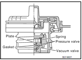
- Turn ignition switch OFF.
- Remove fuel filler cap. Refer to FL-10, "Exploded View".
- Wipe clean valve housing.
- Install fuel filler cap adapter (commercial service tool) to fuel filler cap.
- Check valve opening pressure and vacuum.
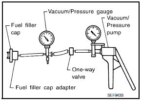
Pressure: 15.3 - 20.0 kPa (0.156 - 0.204 kg/cm2, 2.22 -
2.90 psi)
Vacuum: −6.0 to −3.3 kPa (−0.061 to −0.034 kg/cm2,
−0.87 to −0.48 psi)
2.REPLACE FUEL FILLER CAP
Replace fuel filler cap.
CAUTION: Use only a genuine fuel filler cap as a replacement. If an incorrect fuel filler cap is used, the MIL may illuminate.
DRAIN FILTER
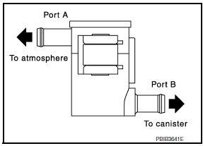
- Check visually for insect nests in the drain filter air inlet.
- Check visually for cracks or flaws in the appearance.
- Check visually for cracks or flaws in the hose.
- Blow air into port A and check that it flows freely out of port B.
- Block port B.
- Blow air into port A and check that there is no leakage.
- If NG, replace drain filter.
 P0455 evap control system
DTC Logic
DTC DETECTION LOGIC
This diagnosis detects a very large leakage (fuel filler cap fell off etc.)
in EVAP system between the fuel tank
and EVAP canister purge volume control solenoid val ...
 P0460 fuel level sensor
Description
The fuel level sensor is mounted in the fuel level sensor unit.
The sensor detects a fuel level in the fuel tank and transmits a signal to the
combination meter. The combination
me ...
Other materials:
P2119 electric throttle control actuator
Description
Electric throttle control actuator consists of throttle control motor,
throttle position sensor, etc.
The throttle control motor is operated by the ECM and it opens and closes the
throttle valve.
The throttle position sensor detects the throttle valve position, and the
openi ...
EBD
System Diagram
System Description
Electric Brake force Distribution functions as follows:
ABS actuator and electric unit (control unit) detects subtle
slippages between the front and rear wheels during
braking. Then it electronically controls the rear braking force (brake fluid
pr ...
Shift lock system
Description
The selector lever cannot be shifted from "P" position to
any other position unless the ignition switch is in the
ON position and the brake pedal is depressed.
Component Function Check
1. CHECK CVT SHIFT LOCK OPERATION
Turn ignition switch ON.
Move selec ...
Nissan Maxima Owners Manual
- Illustrated table of contents
- Safety-Seats, seat belts and supplemental restraint system
- Instruments and controls
- Pre-driving checks and adjustments
- Monitor, climate, audio, phone and voice recognition systems
- Starting and driving
- In case of emergency
- Appearance and care
- Do-it-yourself
- Maintenance and schedules
- Technical and consumer information
Nissan Maxima Service and Repair Manual

0.0109