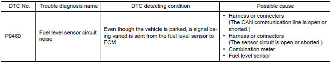
Nissan Maxima Service and Repair Manual: P0460 fuel level sensor
Description
The fuel level sensor is mounted in the fuel level sensor unit.
The sensor detects a fuel level in the fuel tank and transmits a signal to the combination meter. The combination meter sends the fuel level sensor signal to the ECM via the CAN communication line.
It consists of two parts, one is mechanical float and the other is variable resistor. Fuel level sensor output voltage changes depending on the movement of the fuel mechanical float.
DTC Logic
DTC DETECTION LOGIC
NOTE:
- If DTC P0460 is displayed with DTC UXXXX, first perform the
trouble diagnosis for DTC UXXXX.
Refer to EC-161, "DTC Logic".
- If DTC P0460 is displayed with DTC P0607, first perform the trouble diagnosis for DTC P0607. Refer to EC-393, "DTC Logic".
When the vehicle is parked, the fuel level in the fuel tank is naturally stable. It means that output signal of the fuel level sensor does not change. If ECM senses sloshing signal from the sensor, fuel level sensor malfunction is detected.
DTC CONFIRMATION PROCEDURE
1.PRECONDITIONING
If DTC Confirmation Procedure has been previously conducted, always perform the following before conducting the next test.
- Turn ignition switch OFF and wait at least 10 seconds.
- Turn ignition switch ON.
- Turn ignition switch OFF and wait at least 10 seconds.
2.PERFORM DTC CONFIRMATION PROCEDURE
- Start engine and wait maximum of 2 consecutive minutes.
- Check 1st trip DTC.
Diagnosis Procedure
1.CHECK COMBINATION METER FUNCTION
2.CHECK INTERMITTENT INCIDENT
 P0456 evap control system
DTC Logic
DTC DETECTION LOGIC
NOTE:
If DTC P0456 is displayed with DTC P0442, first perform the trouble diagnosis
for DTC P0456.
This diagnosis detects very small leakage in the EVAP line betwe ...
 P0461 fuel level sensor
Description
The fuel level sensor is mounted in the fuel level sensor unit.
The sensor detects a fuel level in the fuel tank and transmits a signal to the
combination meter. The combination
me ...
Other materials:
BCM branch line circuit
Diagnosis Procedure
1.CHECK CONNECTOR
Turn the ignition switch OFF.
Disconnect the battery cable from the negative terminal.
Check the terminals and connectors of the BCM for damage, bend and
loose connection (unit side and
connector side).
2.CHECK HARNESS FOR OPEN CIRCUIT
Disc ...
P2101 electric throttle control function
Description
Electric throttle control actuator consists of throttle control motor,
throttle position sensor, etc.
The throttle control motor is operated by the ECM and it opens and closes the
throttle valve.
The current opening angle of the throttle valve is detected by the throttle
pos ...
B260f engine status
Description
BCM receives the engine status signal from ECM via CAN
communication.
DTC Logic
DTC DETECTION LOGIC
NOTE:
If DTC B260F is displayed with DTC
U1000, first perform the trouble diagnosis for DTC U1000. Refer to
SEC-29, "DTC Logic".
If DTC B260F is displayed with D ...
Nissan Maxima Owners Manual
- Illustrated table of contents
- Safety-Seats, seat belts and supplemental restraint system
- Instruments and controls
- Pre-driving checks and adjustments
- Monitor, climate, audio, phone and voice recognition systems
- Starting and driving
- In case of emergency
- Appearance and care
- Do-it-yourself
- Maintenance and schedules
- Technical and consumer information
Nissan Maxima Service and Repair Manual

0.0064