Nissan Maxima Service and Repair Manual: P0703 brake switch B
Description
BCM detects ON/OFF state of the stop lamp switch and transmits the data to the TCM via CAN communication by converting the data to a signal.
DTC Logic
DTC DETECTION LOGIC
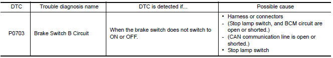
DTC CONFIRMATION PROCEDURE
CAUTION: Always drive vehicle at a safe speed.
NOTE: Immediately after performing any "DTC CONFIRMATION PROCEDURE", always turn ignition switch OFF.
Then wait at least 10 seconds before performing the next test.
1.CHECK DTC DETECTION
 With CONSULT
- Turn ignition switch ON.
- Start engine.
- Drive vehicle for at least 3 consecutive seconds.
- Perform "Self Diagnostic Results" in "TRANSMISSION".
Diagnosis Procedure
Regarding Wiring Diagram information, refer to TM-126, "Wiring Diagram".
1.CHECK STOP LAMP SWITCH CIRCUIT
- Check and adjust the installation position of stop lamp switch. Refer to BR-14, "Inspection and Adjustment".
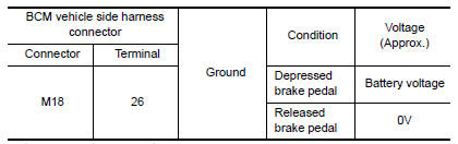
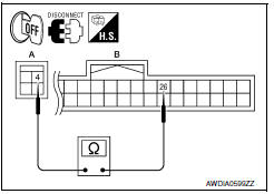
- Disconnect BCM connector.
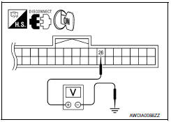
- Check voltage between BCM vehicle side harness connector terminal and ground.
2.CHECK HARNESS BETWEEN STOP LAMP SWITCH AND BCM (PART 1)
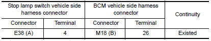
- Disconnect stop lamp switch connector.
- Check continuity between stop lamp switch vehicle side harness connector terminal and BCM vehicle side harness connector terminal.
3.CHECK HARNESS BETWEEN STOP LAMP SWITCH AND BCM (PART 2)
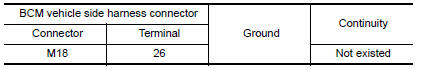
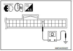
Check continuity between BCM vehicle side harness connector terminal and ground.
4.CHECK STOP LAMP SWITCH
Check stop lamp switch. Refer to TM-48, "Component Inspection (Stop Lamp Switch)".
5.CHECK BCM
 With CONSULT
- Turn ignition switch OFF.
- Connect BCM connector.
- Turn ignition switch ON.
- Select "BRAKE SW 1" in "Data Monitor" in "BCM" and verify the proper operation of ON/OFF. Refer to BCS-41, "Reference Value".
6.DETECT MALFUNCTIONING ITEMS
Check TCM connector pin terminals for damage or loose connection with harness connector.
Component Inspection (Stop Lamp Switch)
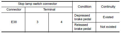
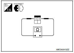
1.CHECK STOP LAMP SWITCH
Check continuity between stop lamp switch connector terminals.
 P0615 starter relay
Description
TCM controls starter relay in IPDM E/R.
TCM switches starter relay ON at "P" or "N" position and allows to
crank engine.
Then it prohibits cranking other than ...
 P0705 transmission range switch A
Description
The Transmission range switch is included in the control valve
assembly.
The Transmission range switch includes 4 transmission position
switches.
TCM judges ...
Other materials:
Jump starting
To start your engine with a booster battery, the
instructions and precautions below must be followed.
WARNING
If done incorrectly, jump starting can
lead to a battery explosion, resulting in
severe injury or death. It could also
damage your vehicle.
Explosive hydrogen gas is always pre ...
Daytime running light system
Wiring Diagram
...
Rear view monitor system
System Diagram
System Description
When the shift selector is in the R position, the display shows a view to the
rear of the vehicle. Lines which indicate the vehicle clearance and distances
are also displayed.
Component Parts Location
Tweeter LH M143
Tweeter RH M144
AV control ...
Nissan Maxima Owners Manual
- Illustrated table of contents
- Safety-Seats, seat belts and supplemental restraint system
- Instruments and controls
- Pre-driving checks and adjustments
- Monitor, climate, audio, phone and voice recognition systems
- Starting and driving
- In case of emergency
- Appearance and care
- Do-it-yourself
- Maintenance and schedules
- Technical and consumer information
Nissan Maxima Service and Repair Manual

0.0056