Nissan Maxima Owners Manual: How to read the displayed lines

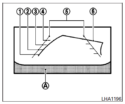
Guiding lines which indicate the vehicle width and distances to objects with reference to the vehicle body line A are displayed on the monitor.
Distance guide lines
Indicate distances from the vehicle body.
- Red line 1 : approx. 1.5 ft (0.5 m)
- Yellow line 2 : approx. 3 ft (1 m)
- Green line 3 : approx. 7 ft (2 m)
- Green line 4 : approx. 10 ft (3 m)
Vehicle width guide lines
Indicate the vehicle width when backing up.
Predicted course lines
Indicate the predicted course when backing up.
The predicted course lines will be displayed on the monitor when the shift lever is in the R (Reverse) position and the steering wheel is turned.
The predicted course lines will move depending on how much the steering wheel is turned and will not be displayed while the steering wheel is in the straight-ahead position.
The vehicle width guide lines and the width of the predicted course lines are wider than the actual width and course.
 RearView Monitor (if so equipped)
1. CAMERA button
WARNING
Failure to follow the warnings and instructions
for proper use of the Rear-
View Monitor system could result in serious
injury or death.
RearView Monitor is a ...
 Difference between predicted and actual distances
The displayed guidelines and their locations on
the ground are for approximate reference only.
Objects on uphill or downhill surfaces or projecting
objects will be actually located at distances
...
Other materials:
Rear door speaker
Description
The AV control unit sends audio signals to the BOSE speaker amp. The BOSE
speaker amp. amplifies the
audio signals before sending them to the rear door speakers using the audio
signal circuits.
Diagnosis Procedure
1.CONNECTOR CHECK
Check the AV control unit, BOSE speaker amp. a ...
Removal and installation
EXHAUST SYSTEM
Exploded View
Front exhaust tube
Ring gasket
Front exhaust tube stay
Front exhaust tube bracket
Gasket
Center exhaust tube rubber hanger
Center exhaust tube
Center exhaust tube hanger
Rear muffler bracket (RH)
Rear muffler (RH)
Rear muffler bracket (LH) ...
Drive belt
VQ35DE engine
1. Crankshaft pulley
2. Drive belt automatic tensioner pulley
3. Generator pulley
4. Air conditioner compressor pulley
WARNING
Be sure the ignition switch is placed in the
OFF or LOCK position before servicing
drive belt. The engine could rotate
unexpectedly.
1. Visually ...
Nissan Maxima Owners Manual
- Illustrated table of contents
- Safety-Seats, seat belts and supplemental restraint system
- Instruments and controls
- Pre-driving checks and adjustments
- Monitor, climate, audio, phone and voice recognition systems
- Starting and driving
- In case of emergency
- Appearance and care
- Do-it-yourself
- Maintenance and schedules
- Technical and consumer information
Nissan Maxima Service and Repair Manual
0.006
