Nissan Maxima Service and Repair Manual: Rear door speaker
Description
The AV control unit sends audio signals to the BOSE speaker amp. The BOSE speaker amp. amplifies the audio signals before sending them to the rear door speakers using the audio signal circuits.
Diagnosis Procedure
1.CONNECTOR CHECK
Check the AV control unit, BOSE speaker amp. and speaker connectors for the following:
- Proper connection
- Damage
- Disconnected or loose terminals
2.HARNESS CHECK
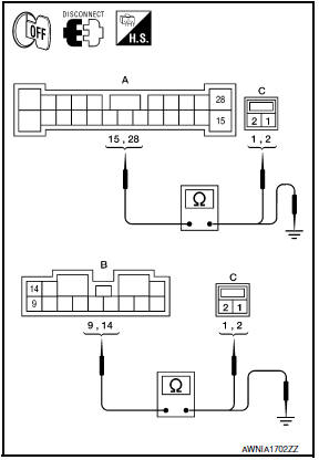
- Disconnect BOSE speaker amp. connectors B109, B110 and suspect speaker connector.
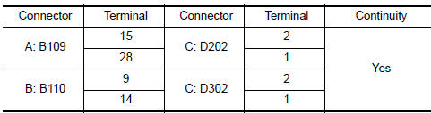
- Check continuity between BOSE speaker amp. harness connectors B109 (A) and B110 (B) and suspect speaker harness connector (C).
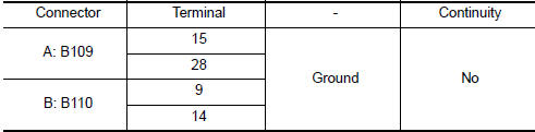
- Check continuity between BOSE speaker amp. harness connectors B109 (A) and B110 (B) and ground.
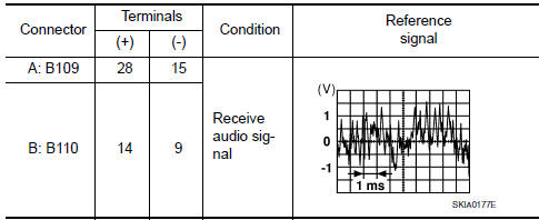
3.REAR DOOR SPEAKER SIGNAL CHECK
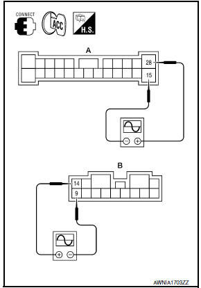
- Connect BOSE speaker amp. connectors and suspect speaker connector.
- Turn ignition switch to ACC.
- Push POWER switch.
- Check the signal between BOSE speaker amp. harness connectors B109 (A) and B110 (B) terminals with CONSULT or oscilloscope.
4.HARNESS CHECK
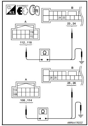
- Disconnect AV control unit connector M157 and BOSE speaker amp. connector B109.
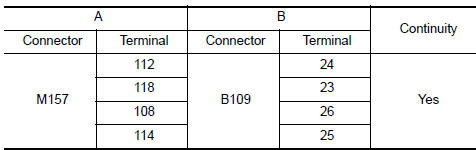
- Check continuity between AV control unit harness connector M157 (A) and BOSE speaker amp. harness connector B109 (B).
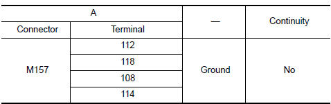
- Check continuity between AV control unit harness connector M157 (A) and ground.
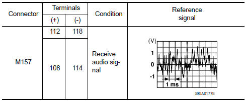
5.REAR DOOR SPEAKER SIGNAL CHECK
- Connect AV control unit connector M157 and BOSE speaker amp. connector B109.
- Turn ignition switch to ACC.
- Push POWER switch.
- Check the signal between AV control unit harness connector terminals with CONSULT or oscilloscope.
 Center speaker
Description
The AV control unit sends audio signals to the BOSE speaker amp. The BOSE
speaker amp. amplifies the
audio signals before sending them to the center speaker using the audio signal
c ...
 Subwoofer
Description
The AV control unit sends audio signals to the BOSE speaker amp. The BOSE
speaker amp. amplifies the
audio signals before sending them to the subwoofers using the audio signal
circu ...
Other materials:
Intelligent key interlock function
INTELLIGENT KEY INTERLOCK FUNCTION : System
INTELLIGENT KEY INTERLOCK FUNCTION : System Description
OUTLINE
When unlocking doors by using Intelligent Key or door request switch (driver
side), seat slide and steering tilt move directly to the exit assist
function.
Other loads move to the ...
Vehicle speed signal circuit
Description
Combination meter sends vehicle speed signal to power steering control unit.
Diagnosis Procedure
1.PERFORM COMBINATION METER SELF-DIAGNOSIS
Perform combination meter self-diagnosis.
2.CHECK HARNESS BETWEEN COMBINATION METER AND POWER STEERING CONTROL UNIT FOR
OPEN
Turn the ...
Clip list
Descriptions for Clips
Replace any clips which are damaged during removal or installation.
...
Nissan Maxima Owners Manual
- Illustrated table of contents
- Safety-Seats, seat belts and supplemental restraint system
- Instruments and controls
- Pre-driving checks and adjustments
- Monitor, climate, audio, phone and voice recognition systems
- Starting and driving
- In case of emergency
- Appearance and care
- Do-it-yourself
- Maintenance and schedules
- Technical and consumer information
Nissan Maxima Service and Repair Manual

0.0061