Nissan Maxima Service and Repair Manual: Subwoofer
Description
The AV control unit sends audio signals to the BOSE speaker amp. The BOSE speaker amp. amplifies the audio signals before sending them to the subwoofers using the audio signal circuits.
Diagnosis Procedure
1.CONNECTOR CHECK
Check the AV control unit, BOSE speaker amp. and subwoofer connectors for the following:
- Proper connection
- Damage
- Disconnected or loose terminals
2.HARNESS CHECK
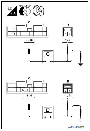
- Disconnect BOSE speaker amp. connector B110 and suspect rear subwoofer connector.
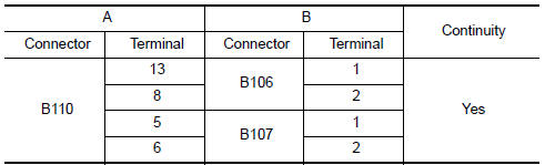
- Check continuity between BOSE speaker amp. harness connector B110 (A) and suspect rear subwoofer harness connector (B).
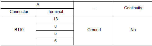
- Check continuity between BOSE speaker amp. harness connector B110 (A) and ground
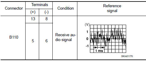
3.REAR SUBWOOFER SIGNAL CHECK
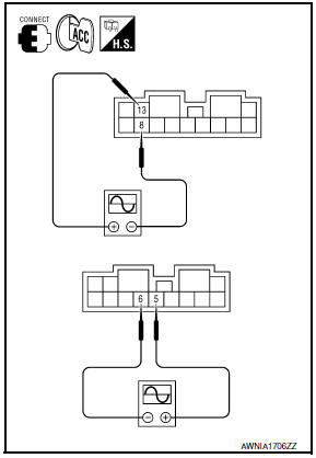
- Connect BOSE speaker amp. connector B110 and suspect rear subwoofer connector.
- Turn ignition switch to ACC.
- Push POWER switch.
- Check the signal between BOSE speaker amp. harness connector B110 terminals with CONSULT or oscilloscope.
4.HARNESS CHECK
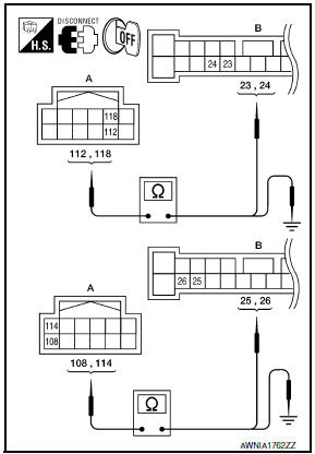
- Disconnect AV control unit connector M157 and BOSE speaker amp. connector B109.
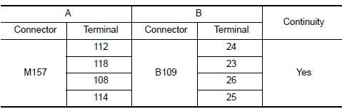
- Check continuity between AV control unit harness connector M157 (A) and BOSE speaker amp. harness connector B109 (B).
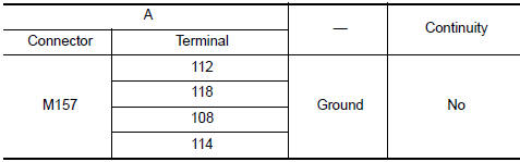
- Check continuity between AV control unit harness connector M157 (A) terminal and ground
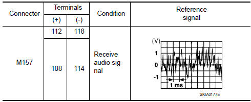
5.REAR SUBWOOFER SIGNAL CHECK
- Connect AV control unit connector M157 and BOSE speaker amp. connector B109.
- Turn ignition switch to ACC.
- Push POWER switch.
- Check the signal between AV control unit harness connector terminals with CONSULT or oscilloscope.
 Rear door speaker
Description
The AV control unit sends audio signals to the BOSE speaker amp. The BOSE
speaker amp. amplifies the
audio signals before sending them to the rear door speakers using the audio
sign ...
 AMP on signal circuit
Description
When the audio system is turned on, a voltage signal is supplied from the AV
control unit to the BOSE speaker
amp. When this signal is received, the BOSE speaker amp. will turn on.
D ...
Other materials:
MOD system operation
The MOD system will turn on automatically under
the following conditions:
When the shift lever is in the R (Reverse)
position.
When vehicle speed decreases below approximately
6 mph (10 km/h) and the camera
screen is displayed.
Front and bird's-eye views
The MOD system operates ...
Diagnosis and repair workflow
Work Flow
OVERALL SEQUENCE
1.GET INFORMATION FOR SYMPTOM
Get the detailed information from the customer about the symptom (the
condition and the environment when
the incident/malfunction occurred).
2.CHECK DTC WITH BCM AND IPDM E/R
Check "Self Diagnostic Result" with CONSULT.
Perform ...
Basic inspection
DIAGNOSIS AND REPAIR WORKFLOW
Work Flow
OVERALL SEQUENCE
DETAILED FLOW
1.INTERVIEW FOR MALFUNCTION
Find out what the customer's concerns are.
2.SYMPTOM CHECK
Verify the symptom from the customer's information.
3.BASIC INSPECTION
Check the operation of each part. Check if any concerns occu ...
Nissan Maxima Owners Manual
- Illustrated table of contents
- Safety-Seats, seat belts and supplemental restraint system
- Instruments and controls
- Pre-driving checks and adjustments
- Monitor, climate, audio, phone and voice recognition systems
- Starting and driving
- In case of emergency
- Appearance and care
- Do-it-yourself
- Maintenance and schedules
- Technical and consumer information
Nissan Maxima Service and Repair Manual

0.0062