Nissan Maxima Owners Manual: Difference between predicted and actual distances
The displayed guidelines and their locations on the ground are for approximate reference only.
Objects on uphill or downhill surfaces or projecting objects will be actually located at distances different from those displayed in the monitor relative to the guidelines (refer to illustrations). When in doubt, turn around and view the objects as you are backing up, or park and exit the vehicle to view the positioning of objects behind the vehicle.
Backing up on a steep uphill
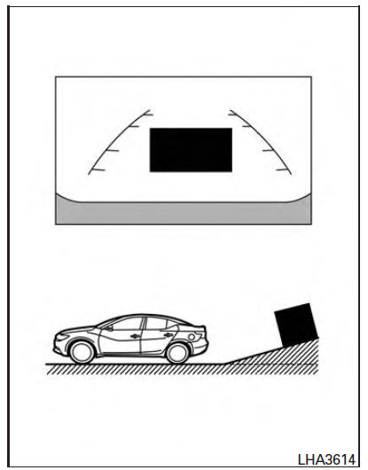
When backing up the vehicle up a hill, the distance guide lines and the vehicle width guide lines are shown closer than the actual distance.
Note that any object on the hill is further than it appears on the monitor.
Backing up on a steep downhill
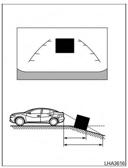
When backing up the vehicle down a hill, the distance guide lines and the vehicle width guide lines are shown farther than the actual distance.
Note that any object on the hill is closer than it appears on the monitor.
Backing up near a projecting object
The predicted course lines A do not touch the object in the display. However, the vehicle may hit the object if it projects over the actual backing up course.
Backing up behind a projecting object
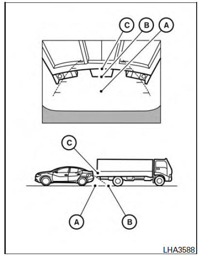
The position C is shown farther than the position B in the display. However, the position C is actually at the same distance as the position A .
The vehicle may hit the object when backing up to the position A if the object projects over the actual backing up course.
 How to read the displayed lines
Guiding lines which indicate the vehicle width
and distances to objects with reference to the
vehicle body line A are displayed on the monitor.
Distance guide lines
Indicate distances from the ...
 How to park with predicted course lines
WARNING
If the tires are replaced with different
sized tires, the predicted course lines
may be displayed incorrectly.
On a snow-covered or slippery road,
there may be a difference between the
p ...
Other materials:
Climate controlled seat switch indicator
Description
Illuminates the climate controlled seat switch to indicate operating status.
Component Function Check
1.CHECK CLIMATE CONTROLLED SEAT SWITCH INDICATOR FUNCTION
Check that the indicators for the climate controlled seat switch operate in
both COOL and HEAT modes.
Diagnosis Procedure ...
Inspection and adjustment
ADDITIONAL SERVICE WHEN REPLACING CONTROL UNIT
ADDITIONAL SERVICE WHEN REPLACING CONTROL UNIT : Description
BEFORE REPLACEMENT
When replacing AV control unit, save current vehicle specification with
CONSULT configuration before
replacement.
AFTER REPLACEMENT
CAUTION:
When replacing AV con ...
Front disc brake
BRAKE PAD
BRAKE PAD : Inspection of Pad
PAD WEAR
Check pad thickness from the inspection hole on cylinder body.
Check using a scale if necessary
DISC ROTOR
DISC ROTOR : Inspection of Rotor
VISUAL
Check surface of disc rotor for uneven wear, cracks, and serious damage.
Replace as ne ...
Nissan Maxima Owners Manual
- Illustrated table of contents
- Safety-Seats, seat belts and supplemental restraint system
- Instruments and controls
- Pre-driving checks and adjustments
- Monitor, climate, audio, phone and voice recognition systems
- Starting and driving
- In case of emergency
- Appearance and care
- Do-it-yourself
- Maintenance and schedules
- Technical and consumer information
Nissan Maxima Service and Repair Manual

0.0059