Nissan Maxima Service and Repair Manual: P2101 electric throttle control function
Description
Electric throttle control actuator consists of throttle control motor, throttle position sensor, etc.
The throttle control motor is operated by the ECM and it opens and closes the throttle valve.
The current opening angle of the throttle valve is detected by the throttle position sensor. The throttle position sensor provides feedback to the ECM, when opens/closes the throttle valve in response to driving conditions via the throttle control motor.
DTC Logic
DTC DETECTION LOGIC
NOTE:
- If DTC P2101 is displayed with DTC P2100, first perform the trouble diagnosis for DTC P2100. Refer to EC-456, "DTC Logic".
- If DTC P2101 is displayed with DTC 2119, first perform the trouble diagnosis for DTC P2119. Refer to EC-465, "DTC Logic".
DTC CONFIRMATION PROCEDURE
1.PRECONDITIONING
If DTC Confirmation Procedure has been previously conducted, always perform the following before conducting the next test.
- Turn ignition switch OFF and wait at least 10 seconds.
- Turn ignition switch ON.
- Turn ignition switch OFF and wait at least 10 seconds.
TESTING CONDITION: Before performing the following procedure, confirm that battery voltage is more than 11 V when engine is running.
2.PERFORM DTC CONFIRMATION PROCEDURE
- Turn ignition switch ON and wait at least 2 seconds.
- Start engine and let it idle for 5 seconds.
- Check DTC.
Diagnosis Procedure
1.CHECK GROUND CONNECTION
- Turn ignition switch OFF.
- Check ground connection E9.
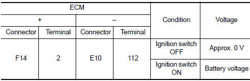
2.CHECK THROTTLE CONTROL MOTOR RELAY INPUT SIGNAL CIRCUIT-I
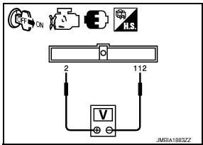
- Check the voltage between ECM harness connectors.
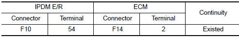
3.CHECK THROTTLE CONTROL MOTOR RELAY POWER SUPPLY CIRCUIT-II
- Turn ignition switch OFF.
- Disconnect ECM harness connector.
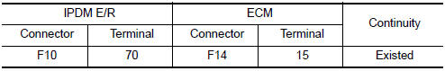
- Disconnect IPDM E/R harness connector.
- Check the continuity between IPDM E/R harness connector and ECM harness connector.
- Also check harness for short to ground and short to power.
4.CHECK THROTTLE CONTROL MOTOR RELAY INPUT SIGNAL CIRCUIT-II
- Check the continuity between IPDM E/R harness connector and ECM harness connector.
- Also check harness for short to ground and short to power.
5.CHECK FUSE
- Disconnect 15 A fuse (No. 43) from IPDM E/R.
- Check if 15 A fuse is blown.
6.CHECK INTERMITTENT INCIDENT
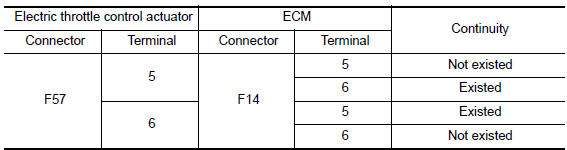
7.CHECK THROTTLE CONTROL MOTOR OUTPUT SIGNAL CIRCUIT FOR OPEN OR SHORT
- Turn ignition switch OFF.
- Disconnect electric throttle control actuator harness connector.
- Disconnect ECM harness connector.
- Check the continuity between electric throttle control actuator harness connector and ECM harness connector.
- Also check harness for short to ground and short to power.
8.CHECK ELECTRIC THROTTLE CONTROL ACTUATOR VISUALLY
- Remove the intake air duct. Refer to EM-24, "Removal and Installation".
- Check if foreign matter is caught between the throttle valve (1) and the housing.
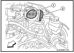
2: Electric throttle control actuator
 : Vehicle front
9.CHECK THROTTLE CONTROL MOTOR
10.CHECK INTERMITTENT INCIDENT
11.REPLACE ELECTRIC THROTTLE CONTROL ACTUATOR
- Replace electric throttle control actuator
Component Inspection
1.CHECK THROTTLE CONTROL MOTOR
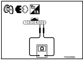
- Turn ignition switch OFF.
- Disconnect electric throttle control actuator harness connector
- Check resistance between electric throttle control actuator terminals as per the following.

2.REPLACE ELECTRIC THROTTLE CONTROL ACTUATOR
- Replace electric throttle control actuator
Special Repair Requirement
1.PERFORM THROTTLE VALVE CLOSED POSITION LEARNING
2.PERFORM IDLE AIR VOLUME LEARNING
 P2100, P2103 throttle control motor relay
Description
Power supply for the throttle control motor is provided to the ECM via the
throttle control motor relay. The throttle
control motor relay is controlled ON/OFF by the ECM. When the ign ...
 P2118 throttle control motor
Description
The throttle control motor is operated by the ECM and it opens and closes the
throttle valve.
The current opening angle of the throttle valve is detected by the throttle
position s ...
Other materials:
Tweeter
Description
The AV control unit sends audio signals to the BOSE speaker amp. The BOSE
speaker amp. amplifies the
audio signals before sending them to the tweeters using the audio signal
circuits.
Diagnosis Procedure
1.CONNECTOR CHECK
Check the AV control unit, BOSE speaker amp. and speaker ...
Service data and specifications (SDS)
SERVICE DATA AND SPECIFICATIONS (SDS)
General Specifications
Brake Pedal
Check Valve
Brake Booster
Front Disc Brake
Rear Disc Brake
...
Precaution
PRECAUTIONSPrecaution for Supplemental
Restraint System (SRS) "AIR BAG" and "SEAT BELT
PRE-TENSIONER"
The Supplemental Restraint System such as "AIR BAG" and
"SEAT BELT PRE-TENSIONER", used along
with a front seat belt, helps to reduce the risk or severity of injury to the
driver and fron ...
Nissan Maxima Owners Manual
- Illustrated table of contents
- Safety-Seats, seat belts and supplemental restraint system
- Instruments and controls
- Pre-driving checks and adjustments
- Monitor, climate, audio, phone and voice recognition systems
- Starting and driving
- In case of emergency
- Appearance and care
- Do-it-yourself
- Maintenance and schedules
- Technical and consumer information
Nissan Maxima Service and Repair Manual

0.0069