Nissan Maxima Service and Repair Manual: P0615 starter relay
Description
- TCM controls starter relay in IPDM E/R.
- TCM switches starter relay ON at "P" or "N" position and allows to crank engine.
- Then it prohibits cranking other than at "P" or "N" position.
DTC Logic
DTC DETECTION LOGIC
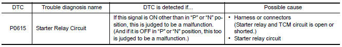
DTC CONFIRMATION PROCEDURE
CAUTION: Always drive vehicle at a safe speed.
NOTE: Immediately after performing any "DTC CONFIRMATION PROCEDURE", always turn ignition switch OFF.
Then wait at least 10 seconds before performing the next test.
1.CHECK DTC DETECTION
 With CONSULT
- Turn ignition switch ON.
- Perform "Self Diagnostic Results" in "TRANSMISSION".
Diagnosis Procedure
Regarding Wiring Diagram information, refer to TM-126, "Wiring Diagram".
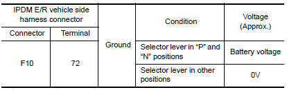
1.CHECK STARTER RELAY SIGNAL
- Turn ignition switch ON.
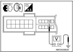
- Disconnect IPDM E/R connector.
- Check voltage between IPDM E/R vehicle side harness connector terminal and ground.
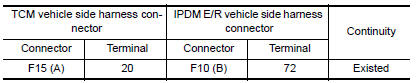
2.CHECK HARNESS BETWEEN TCM AND IPDM E/R (PART 1)
- Turn ignition switch OFF.
- Disconnect TCM connector.
- Check continuity between TCM vehicle side harness connector terminal and IPDM E/R vehicle side harness connector terminal.
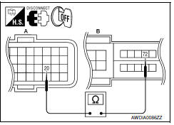
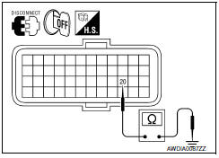
3.CHECK HARNESS BETWEEN TCM AND IPDM E/R (PART 2)
Check continuity between TCM vehicle side harness connector terminal and ground.
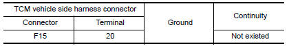
4.DETECT MALFUNCTIONING ITEMS
Check TCM connector pin terminals for damage or loose connection with harness connector.
 U1010 control unit (CAN)
Description
CAN (Controller Area Network) is a serial communication line for real time
application. It is an on-vehicle multiplex
communication line with high data communication speed and excelle ...
 P0703 brake switch B
Description
BCM detects ON/OFF state of the stop lamp switch and transmits the data to
the TCM via CAN communication
by converting the data to a signal.
DTC Logic
DTC DETECTION LOGIC
DTC CON ...
Other materials:
Symptom diagnosis
SQUEAK AND RATTLE TROUBLE DIAGNOSES
Work Flow
CUSTOMER INTERVIEW
Interview the customer if possible, to determine the conditions that exist
when the noise occurs. Use the Diagnostic
Worksheet during the interview to document the facts and conditions when the
noise occurs and any
custome ...
Power seat for passenger side
Wiring Diagram
...
B2636, B2637, B2638, B2639, B2654, B2655 mode door motor
Description
COMPONENT DESCRIPTION
Mode Door Motor
The mode door motor (1) is attached to the heater & cooling unit
assembly.
It rotates so that air is discharged from the outlet set by the
A/C
auto amp. Motor rotation is conveyed to a link which activates the
mode door.
D ...
Nissan Maxima Owners Manual
- Illustrated table of contents
- Safety-Seats, seat belts and supplemental restraint system
- Instruments and controls
- Pre-driving checks and adjustments
- Monitor, climate, audio, phone and voice recognition systems
- Starting and driving
- In case of emergency
- Appearance and care
- Do-it-yourself
- Maintenance and schedules
- Technical and consumer information
Nissan Maxima Service and Repair Manual

0.0071