Nissan Maxima Service and Repair Manual: ECU diagnosis information
BCM (BODY CONTROL MODULE)
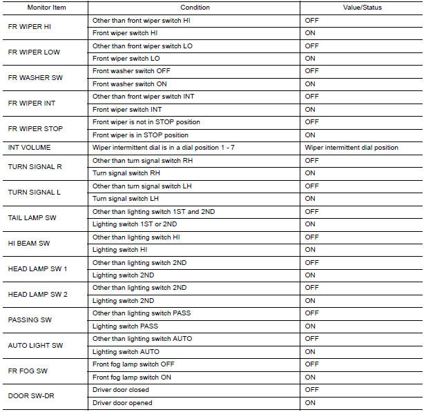
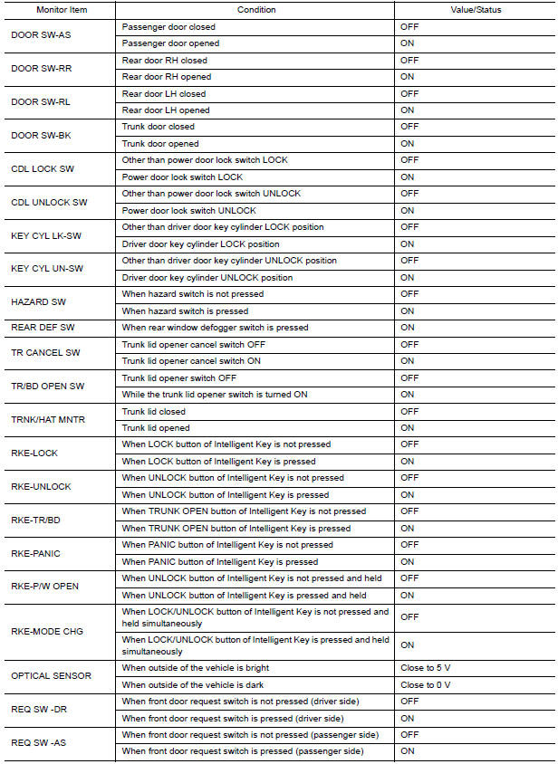
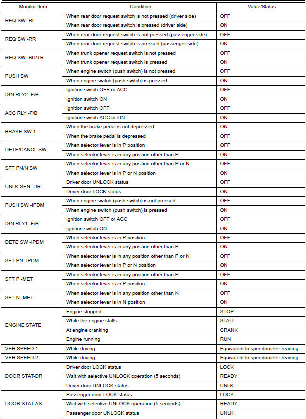
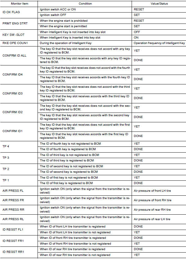
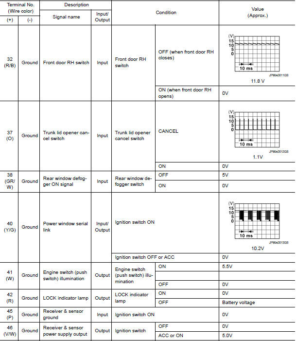
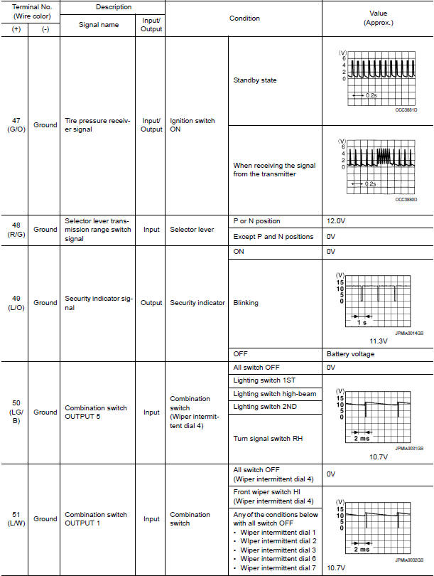
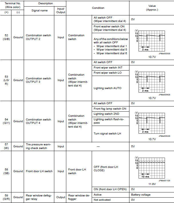
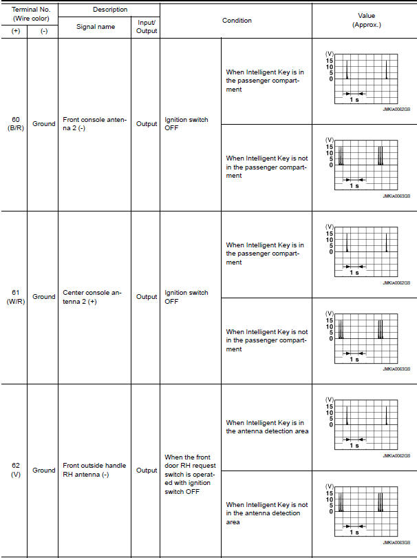
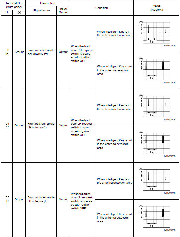
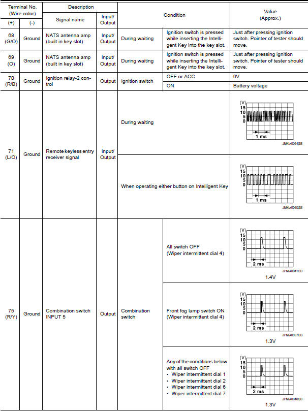
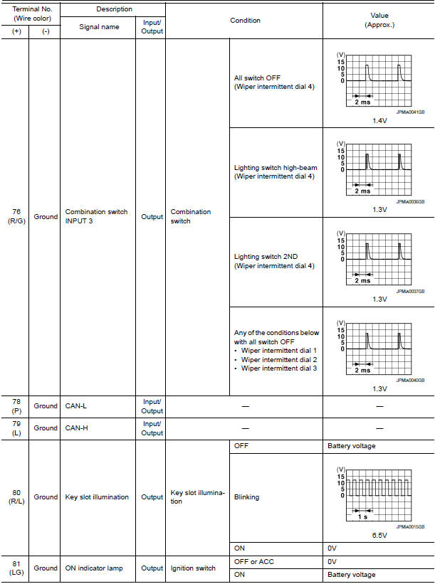
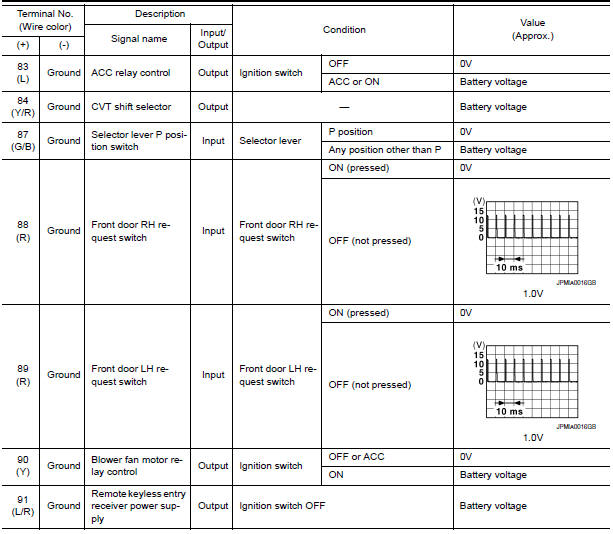
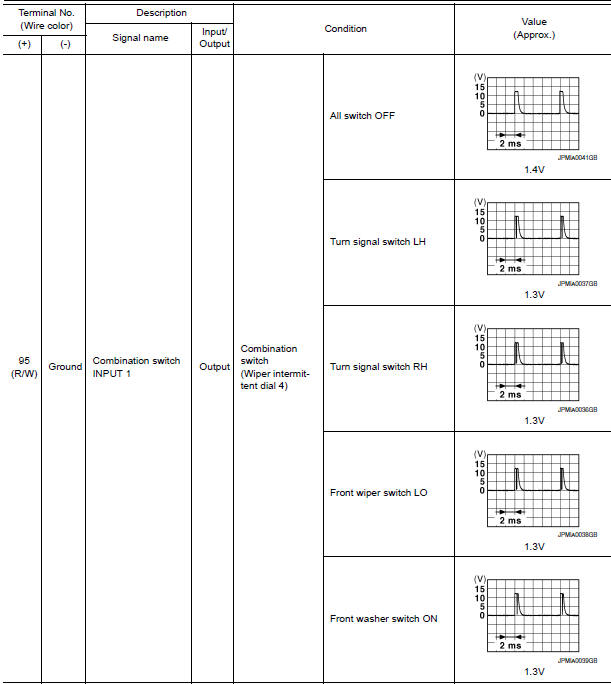
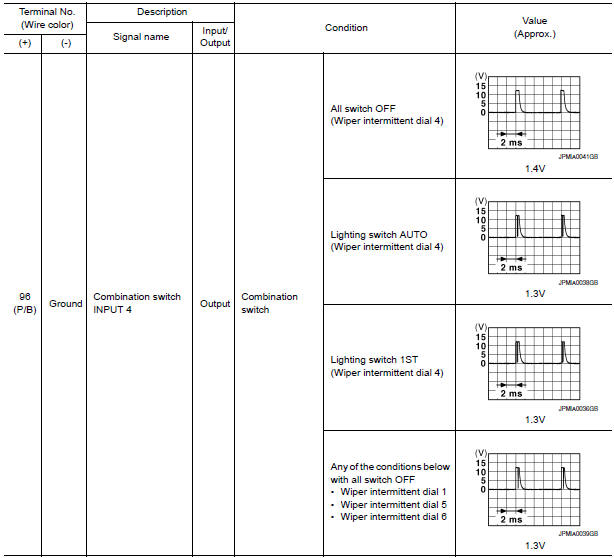
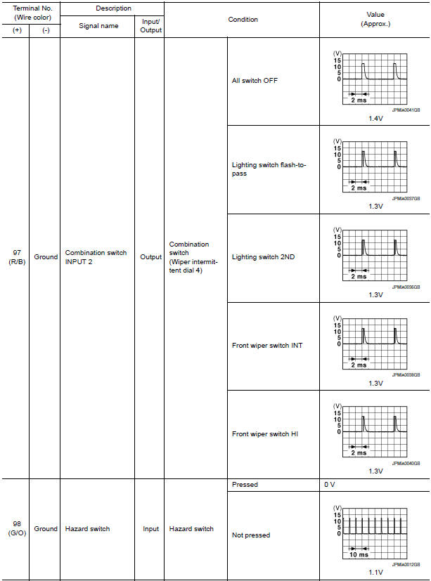
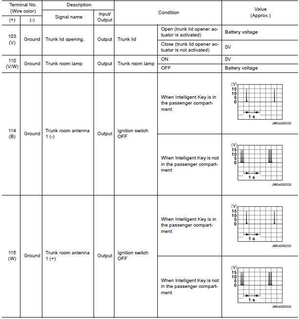
Reference Value
NOTE: The Signal Tech II Tool (J-50190) can be used to perform the following functions. Refer to the Signal Tech II User Guide for additional information.
- Activate and display TPMS transmitter IDs
- Display tire pressure reported by the TPMS transmitter
- Read TPMS DTCs
- Register TPMS transmitter IDs
- Check Intelligent Key relative signal strength
- Confirm vehicle Intelligent Key antenna signal strength
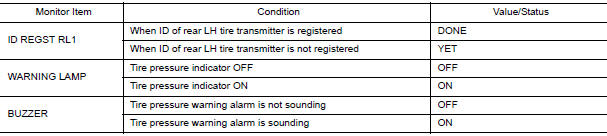
VALUES ON THE DIAGNOSIS TOOL
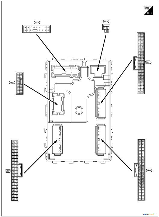
Terminal Layout
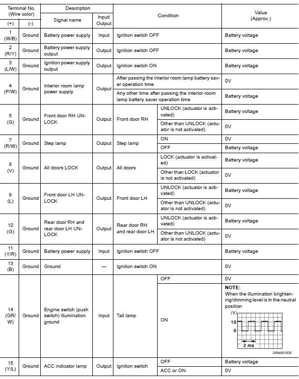
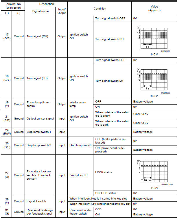
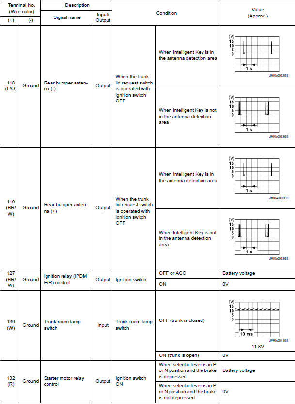
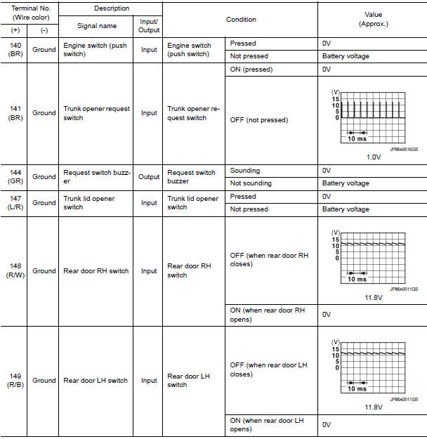
Physical Values
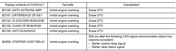
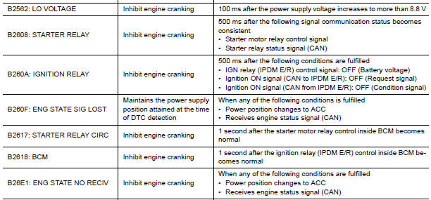
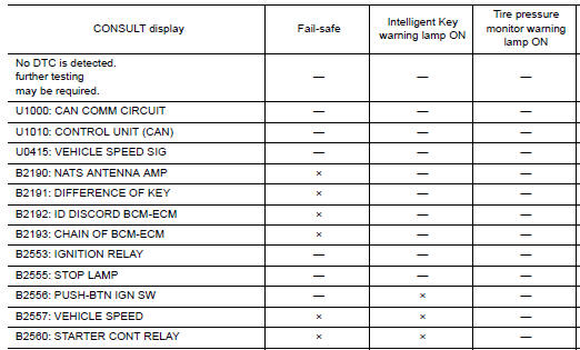
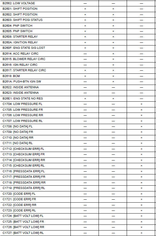
Fail Safe
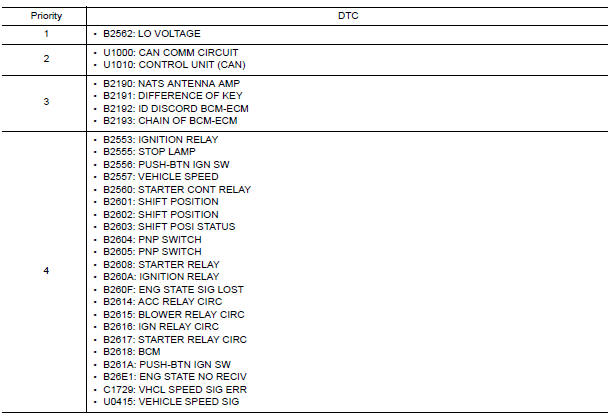
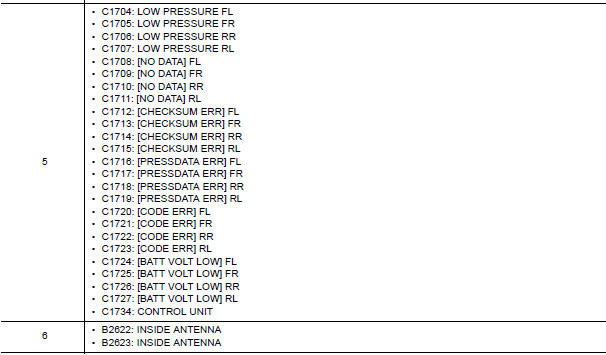
DTC Inspection Priority Chart
If some DTCs are displayed at the same time, perform inspections one by one based on the following priority chart.
DTC Index
NOTE: Details of time display
- CRNT: Displays when there is a malfunction now or after returning to the normal condition until turning ignition switch OFF → ON again.
- 1 - 39: Displayed if any previous malfunction is present when current condition is normal. It increases 1 → 2 → 3...38 → 39 after returning to the normal condition whenever ignition switch OFF → ON. The counter remains at 39 even if the number of cycles exceeds it. It is counted from 1 again when turning ignition switch OFF → ON after returning to the normal condition if the malfunction is detected again.

 Combination switch output circuit
Diagnosis Procedure
1. CHECK OUTPUT 1 - 5 SYSTEM CIRCUIT FOR OPEN
Turn the ignition switch OFF.
Disconnect the BCM and combination switch.
Check continuity between BCM harness connector and c ...
 Wiring diagram
BCM (BODY CONTROL MODULE)
Wiring Diagram
...
Other materials:
Manual shift mode
The transmission enters the manual shift mode by
moving the shift lever to the left side in the "D"
range. You can select the manual shift range
either by moving the shift lever up or down, or by
pulling the right-side or left-side paddle shifter (if
so equipped). To cancel the manual shift ...
Precaution
PRECAUTIONS
Precaution for Supplemental Restraint System (SRS) "AIR BAG" and "SEAT
BELT
PRE-TENSIONER"
The Supplemental Restraint System such as "AIR BAG" and "SEAT BELT PRE-TENSIONER",
used along
with a front seat belt, helps to reduce the risk or severity of injury to ...
System description
FRONT WIPER AND WASHER SYSTEM
System Diagram
System Description
OUTLINE
The front wiper is controlled by each function of BCM and IPDM E/R.
Control by BCM
Combination switch reading function
Front wiper control function
Control by IPDM E/R
Front wiper control function
Relay con ...
Nissan Maxima Owners Manual
- Illustrated table of contents
- Safety-Seats, seat belts and supplemental restraint system
- Instruments and controls
- Pre-driving checks and adjustments
- Monitor, climate, audio, phone and voice recognition systems
- Starting and driving
- In case of emergency
- Appearance and care
- Do-it-yourself
- Maintenance and schedules
- Technical and consumer information
Nissan Maxima Service and Repair Manual

0.0072