Nissan Maxima Service and Repair Manual: Combination switch output circuit
Diagnosis Procedure
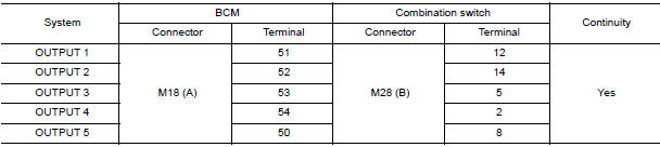
1. CHECK OUTPUT 1 - 5 SYSTEM CIRCUIT FOR OPEN
- Turn the ignition switch OFF.
- Disconnect the BCM and combination switch.
- Check continuity between BCM harness connector and combination switch harness connector
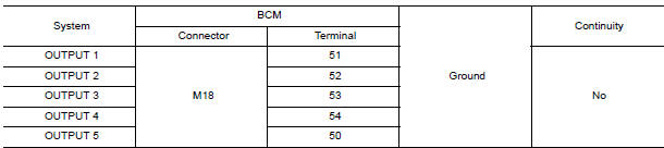
2. CHECK OUTPUT 1 - 5 SYSTEM CIRCUIT FOR SHORT
Check for continuity between BCM harness connector and ground.
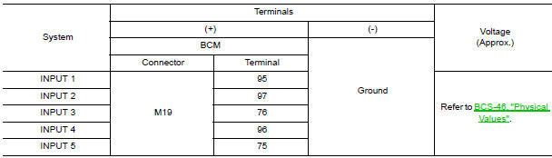
3. CHECK BCM INPUT VOLTAGE
- Connect the BCM and the combination switch connector.
- Check voltage between BCM harness connector and ground.
Special Repair Requirement
1. REQUIRED WORK WHEN REPLACING BCM
 Combination switch input circuit
Diagnosis Procedure
1. CHECK INPUT 1 - 5 SYSTEM CIRCUIT FOR OPEN
Turn the ignition switch OFF.
Disconnect the BCM and combination switch.
Check continuity between BCM harness connector an ...
 ECU diagnosis information
BCM (BODY CONTROL MODULE)
Reference Value
NOTE:
The Signal Tech II Tool (J-50190) can be used to perform the following
functions. Refer to the Signal Tech II
User Guide for additional informat ...
Other materials:
Glove box assembly
Removal and Installation
REMOVAL
Using a suitable tool, gently remove the instrument panel side
finisher (RH).
Open the glove box door and then remove the glove box assembly
screws (A).
Remove the glove box assembly lower screws (A).
Disconnect the harness connectors, then rem ...
Removal and installation
EXHAUST SYSTEM
Exploded View
Front exhaust tube
Ring gasket
Front exhaust tube stay
Front exhaust tube bracket
Gasket
Center exhaust tube rubber hanger
Center exhaust tube
Center exhaust tube hanger
Rear muffler bracket (RH)
Rear muffler (RH)
Rear muffler bracket (LH) ...
Diagnosis system (BCM)
COMMON ITEM
COMMON ITEM : CONSULT Function (BCM - COMMON ITEM)
APPLICATION ITEM
CONSULT performs the following functions via CAN communication with BCM.
SYSTEM APPLICATION
BCM can perform the following functions.
HEADLAMP
HEADLAMP : CONSULT Function (BCM - HEAD LAMP)
DATA MONITOR
ACTI ...
Nissan Maxima Owners Manual
- Illustrated table of contents
- Safety-Seats, seat belts and supplemental restraint system
- Instruments and controls
- Pre-driving checks and adjustments
- Monitor, climate, audio, phone and voice recognition systems
- Starting and driving
- In case of emergency
- Appearance and care
- Do-it-yourself
- Maintenance and schedules
- Technical and consumer information
Nissan Maxima Service and Repair Manual

0.0063