Nissan Maxima Service and Repair Manual: Combination switch input circuit
Diagnosis Procedure
1. CHECK INPUT 1 - 5 SYSTEM CIRCUIT FOR OPEN
- Turn the ignition switch OFF.
- Disconnect the BCM and combination switch.
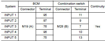
- Check continuity between BCM harness connector and combination switch harness connector.
2. CHECK INPUT 1 - 5 SYSTEM CIRCUIT FOR SHORT
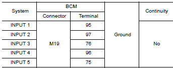
Check for continuity between BCM harness connector and ground.
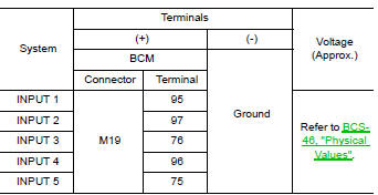
3. CHECK BCM OUTPUT SIGNAL
- Connect the BCM and the combination switch connector.
- Turn ON any switch in the system that is malfunctioning.
- Check voltage between BCM harness connector and ground
Special Repair Requirement
1. REQUIRED WORK WHEN REPLACING BCM
 Power supply and ground circuit
Diagnosis Procedure
1. CHECK FUSE AND FUSIBLE LINK
Check if the following BCM fuses or fusible link are blown
2. CHECK POWER SUPPLY CIRCUIT
Turn ignition switch OFF.
Disconnect BCM.
Che ...
 Combination switch output circuit
Diagnosis Procedure
1. CHECK OUTPUT 1 - 5 SYSTEM CIRCUIT FOR OPEN
Turn the ignition switch OFF.
Disconnect the BCM and combination switch.
Check continuity between BCM harness connector and c ...
Other materials:
Inspection and adjustment
ADDITIONAL SERVICE WHEN REPLACING CONTROL UNIT
ADDITIONAL SERVICE WHEN REPLACING CONTROL UNIT : Description
Initialization of system should be conducted after the following conditions.
When the sunroof motor or sunshade motor is changed.
When the sunroof of sunshade does not operate normally ...
Power door lock system
Wiring Diagram
...
Disassembly and assembly
FUEL LEVEL SENSOR UNIT
Disassembly and Assembly
Fuel Level Sensor Unit
Harness connectors
Fuel level sensor unit
Fuel tank temperature sensor
Float arm assembly
Disassembly
NOTE: Before disassembly, note the proper
placement of the wires to the correct terminals a ...
Nissan Maxima Owners Manual
- Illustrated table of contents
- Safety-Seats, seat belts and supplemental restraint system
- Instruments and controls
- Pre-driving checks and adjustments
- Monitor, climate, audio, phone and voice recognition systems
- Starting and driving
- In case of emergency
- Appearance and care
- Do-it-yourself
- Maintenance and schedules
- Technical and consumer information
Nissan Maxima Service and Repair Manual

0.0054