Nissan Maxima Service and Repair Manual: Power supply and ground circuit
Diagnosis Procedure
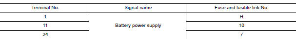
1. CHECK FUSE AND FUSIBLE LINK
Check if the following BCM fuses or fusible link are blown
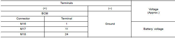
2. CHECK POWER SUPPLY CIRCUIT
- Turn ignition switch OFF.
- Disconnect BCM.
- Check voltage between BCM harness connector and ground.
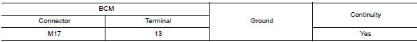
3. CHECK GROUND CIRCUIT
Check continuity between BCM harness connector and ground.
Special Repair Requirement
1. REQUIRED WORK WHEN REPLACING BCM
 B2562 Low voltage
DTC Logic
DTC DETECTION LOGIC
DTC CONFIRMATION PROCEDURE
1. DTC CONFIRMATION
Erase DTC.
Turn ignition switch OFF.
Perform the "SELF-DIAG RESULTS" of BCM with CONSULT, after th ...
 Combination switch input circuit
Diagnosis Procedure
1. CHECK INPUT 1 - 5 SYSTEM CIRCUIT FOR OPEN
Turn the ignition switch OFF.
Disconnect the BCM and combination switch.
Check continuity between BCM harness connector an ...
Other materials:
Road test
Description
DESCRIPTION
The purpose of the test is to determine the
overall performance of
CVT and analyze causes of problems.
The road test consists of the following three
parts:
"Check Before Engine Is Started"TM-164.
"Check at ...
Audio
Some of the information and operations available
on the control panel can also be viewed and
operated on the vehicle information display. The
vehicle information display operations can be
conducted with the switches on the steering
wheel.
Use or
and select
on the vehicle
information disp ...
P1801 vias control solenoid valve 2
Description
The VIAS control solenoid valve 2 cuts the intake manifold vacuum signal for
power valve 2 control. It
responds to ON/OFF signals from the ECM. When the solenoid is OFF, the vacuum
signal from the intake
manifold is cut. When the ECM sends an ON signal the coil pulls the plunger ...
Nissan Maxima Owners Manual
- Illustrated table of contents
- Safety-Seats, seat belts and supplemental restraint system
- Instruments and controls
- Pre-driving checks and adjustments
- Monitor, climate, audio, phone and voice recognition systems
- Starting and driving
- In case of emergency
- Appearance and care
- Do-it-yourself
- Maintenance and schedules
- Technical and consumer information
Nissan Maxima Service and Repair Manual

0.0053