Nissan Maxima Service and Repair Manual: Road test
Description
DESCRIPTION
-
The purpose of the test is to determine the overall performance of CVT and analyze causes of problems.
-
The road test consists of the following three parts:
-
"Check Before Engine Is Started"TM-164.
-
"Check at Idle"TM-165.
-
"Cruise Test"TM-166.
-
-
Before the road test, familiarize yourself with all test procedures and items to check.
-
Perform tests for all the check items until a malfunction phenomenon is detected. Perform diagnosis for NG items after the completion of road tests.
CONSULT SETTING PROCEDURE
-
Using CONSULT, perform a cruise test and record the result.
-
Print the result and ensure that shifts and lock-ups take place as per Shift Schedule.
-
Touch "Data Monitor" in "Direct Diagnostic Mode" screen.
-
Touch "MAIN SIGNALS" to set recording condition.
-
See "Numerical Display", "Barchart Display" or "Line Graph Display".
-
Touch "START".
-
When performing cruise test. Refer to TM-166, "Cruise Test".
-
After finishing cruise test part, touch "RECORD".
-
Touch "STORE".
-
Touch "BACK".
-
Touch "DISPLAY".
-
Touch "PRINT".
-
Check the monitor data printed out.
Check before Engine Is Started
1.CHECK SHIFT POSITION INDICATOR
-
Park vehicle on flat surface.
-
Move selector lever to "P" position.
-
Turn ignition switch OFF. Wait at least 5 seconds.
-
Turn ignition switch ON. (Do not start engine.)
Check at Idle
1.CHECK STARTING THE ENGINE (PART 1)
-
Park vehicle on flat surface.
-
Move selector lever to "P" or "N" position.
-
Turn ignition switch OFF.
-
Turn ignition switch to "START" position.
2.CHECK STARTING THE ENGINE (PART 2)
-
Turn ignition switch ON.
-
Move selector lever to "D", "M", "DS" or "R" position.
-
Turn ignition switch to "START" position.
3.CHECK "P" POSITION FUNCTION
-
Move selector lever to "P" position.
-
Turn ignition switch OFF.
-
Release parking brake.
-
Push vehicle forward or backward.
-
Apply parking brake.
4.CHECK "N" POSITION FUNCTION
-
Start engine.
-
Move selector lever to "N" position.
-
Release parking brake.
5.CHECK SHIFT SHOCK
-
Apply foot brake.
-
Move selector lever to "R" position.
6.CHECK "R" POSITION FUNCTION
Release foot brake for several seconds.
7.CHECK "D" POSITION FUNCTION
Move selector lever to "D", "DS" and "M" position and check if vehicle creeps forward.
Cruise Test
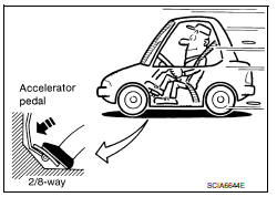
1.CHECK VEHICLE SPEED WHEN SHIFTING GEARS (PART 1)
-
Drive vehicle for approximately 10 minutes to warm engine oil and CVT fluid up to operating temperature.
-
Park vehicle on flat surface.
-
Move selector lever to "P" position.
-
Start engine.
-
Move selector lever to "D" position.
-
Accelerate vehicle at 2/8 throttle opening and check "Vehicle Speed When Shifting Gears".
 With CONSULT
-
Read vehicle speed and engine speed. Refer to TM-194, "Vehicle Speed When Shifting Gears".
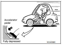
2.CHECK VEHICLE SPEED WHEN SHIFTING GEARS (PART 2)
-
Park vehicle on flat surface.
-
Move selector lever to "D" position.
-
Accelerate vehicle at 8/8 throttle opening and check "Vehicle Speed When Shifting Gears".
 With CONSULT
-
Read vehicle speed and engine speed. Refer to TM-194, "Vehicle Speed When Shifting Gears".
3.CHECK DS MODE FUNCTION
Move to "DS" mode from "D" position.
4.CHECK MANUAL MODE FUNCTION
Move to manual mode from "DS" position.
5.CHECK SHIFT UP FUNCTION
During manual mode driving, is upshift from M1 → M2 → M3 → M4 → M5 → M6 performed?
 With CONSULT
-
Read vehicle speed and engine speed. Refer to TM-38, "CONSULT Function".
6.CHECK SHIFT DOWN FUNCTION
During manual mode driving, is downshift from M6 → M5 → M4 → M3 → M2 → M1 performed?
 With CONSULT
-
Read vehicle speed and engine speed. Refer to TM-38, "CONSULT Function".
7.CHECK ENGINE BRAKE FUNCTION
Check engine brake.
 Line pressure test
Inspection and Judgment
INSPECTION
Line Pressure Test Procedure
Inspect the amount of engine oil and replenish
if necessary.
Drive the car for about 10 minutes to warm ...

Other materials:
Audio system
System Diagram
System Description
AUDIO SYSTEM
The audio system consists of the following components
AV control unit
Display unit
BOSE speaker amp.
Window antenna
Steering wheel audio control switches
A/C and AV switch assembly
Front door speakers
Tweeters
Center speaker
...
U0415 Vehicle speed sig
Description
U0415 is displayed if any unusual condition is present in the reception
status of the vehicle speed signal from
the ABS actuator and electric unit (control unit).
DTC Logic
DTC DETECTION LOGIC
DTC CONFIRMATION PROCEDURE
1. DTC CONFIRMATION
Erase the DTC.
Turn ignition ...
ABS branch line circuit
Diagnosis Procedure
1.CHECK CONNECTOR
Turn the ignition switch OFF.
Disconnect the battery cable from the negative terminal.
Check the terminals and connectors of the ABS actuator and
electric unit (control unit) for damage, bend
and loose connection (unit side and connector side).
...
Nissan Maxima Owners Manual
- Illustrated table of contents
- Safety-Seats, seat belts and supplemental restraint system
- Instruments and controls
- Pre-driving checks and adjustments
- Monitor, climate, audio, phone and voice recognition systems
- Starting and driving
- In case of emergency
- Appearance and care
- Do-it-yourself
- Maintenance and schedules
- Technical and consumer information
Nissan Maxima Service and Repair Manual

0.0054