Nissan Maxima Service and Repair Manual: Door motor
Exploded View
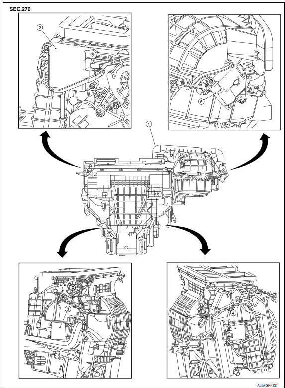
- Heating and cooling unit assembly
- Mode door motor
- Air mix door motor (driver side)
- Air mix door motor (passenger side)
- Intake door motor
INTAKE DOOR MOTOR
INTAKE DOOR MOTOR: Removal and Installation
REMOVAL
- Remove the glove box assembly. Refer to IP-20, "Removal and Installation".
- Remove the remote keyless entry receiver and bracket to reposition out of the way.
- Disconnect the harness connector from the intake door motor.
- Remove the intake door motor screws and the intake door motor from the blower unit.
INSTALLATION
Installation is in the reverse order of removal.
MODE DOOR MOTOR
MODE DOOR MOTOR: Removal and Installation
REMOVAL
- Remove the combination meter. Refer to MWI-122, "Removal and Installation".
- Remove the BCM. Refer to BCS-79, "Removal and Installation".
- Disconnect the harness connector from the mode door motor.
- Remove the mode door motor screws and the mode door motor.
INSTALLATION
Installation is in the reverse order of removal.
AIR MIX DOOR MOTOR
AIR MIX DOOR MOTOR: Removal and Installation - Air Mix Door Motor (Driver Side)
REMOVAL
- Remove the instrument lower panel LH. Refer to IP-19, "Removal and Installation".
- Remove the upper floor connecting duct (LH). Refer to HA-47, "Exploded View".
- Remove the tire pressure receiver.
- Disconnect the harness connector from the air mix door motor.
- Remove the air mix door motor screws and the air mix door motor (driver side).
INSTALLATION
Installation is in the reverse order of removal.
AIR MIX DOOR MOTOR: Removal and Installation - Air Mix Door Motor (Passenger Side)
REMOVAL
- Remove the glove box assembly. Refer to IP-20, "Removal and Installation".
- Remove the upper floor connecting duct (RH). Refer to HA-47, "Exploded View".
- Disconnect the harness connector from the air mix door motor.
- Remove the air mix door motor screws and the air mix door motor (passenger side).
INSTALLATION
Installation is in the reverse order of removal.
 Refrigerant pressure sensor
Removal and Installation
REMOVAL
Discharge the refrigerant. Refer to HA-28, "Recycle Refrigerant".
Remove the core support upper cover.
Disconnect the harness connector from the ref ...
 Body interior
...
Other materials:
Insufficient heating
Component Function Check
Symptom
Insufficient heating
No warm air comes out. (Airflow volume is normal.)
INSPECTION FLOW
1. CONFIRM SYMPTOM BY PERFORMING OPERATION CHECK - TEMPERATURE INCREASE
Press the AUTO switch.
Turn temperature control dial (driver side) clockwise until 32C
...
Front door finisher
Exploded View
Mirror cover
Front door finisher
Step lamp
Arm rest finisher
Main power window and door lock/ unlock switch finisher
Front door grip cover
Seat memory switch (if equipped)
Inside release handle escutcheon
Inside release handle
Flat head screws
&nbs ...
Recommended fluids/lubricants and capacities
The following are approximate capacities. The actual refill capacities may
be slightly different. When refilling, follow the procedure
described in the "Do-it-yourself" section to determine the proper refill
capacity.
...
Nissan Maxima Owners Manual
- Illustrated table of contents
- Safety-Seats, seat belts and supplemental restraint system
- Instruments and controls
- Pre-driving checks and adjustments
- Monitor, climate, audio, phone and voice recognition systems
- Starting and driving
- In case of emergency
- Appearance and care
- Do-it-yourself
- Maintenance and schedules
- Technical and consumer information
Nissan Maxima Service and Repair Manual

0.0052