Nissan Maxima Service and Repair Manual: Bose speaker AMP
Reference Values
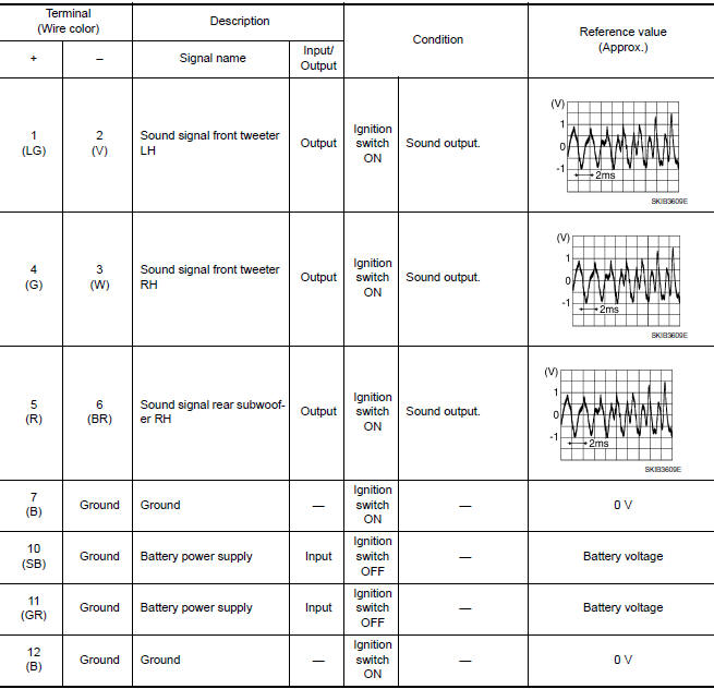
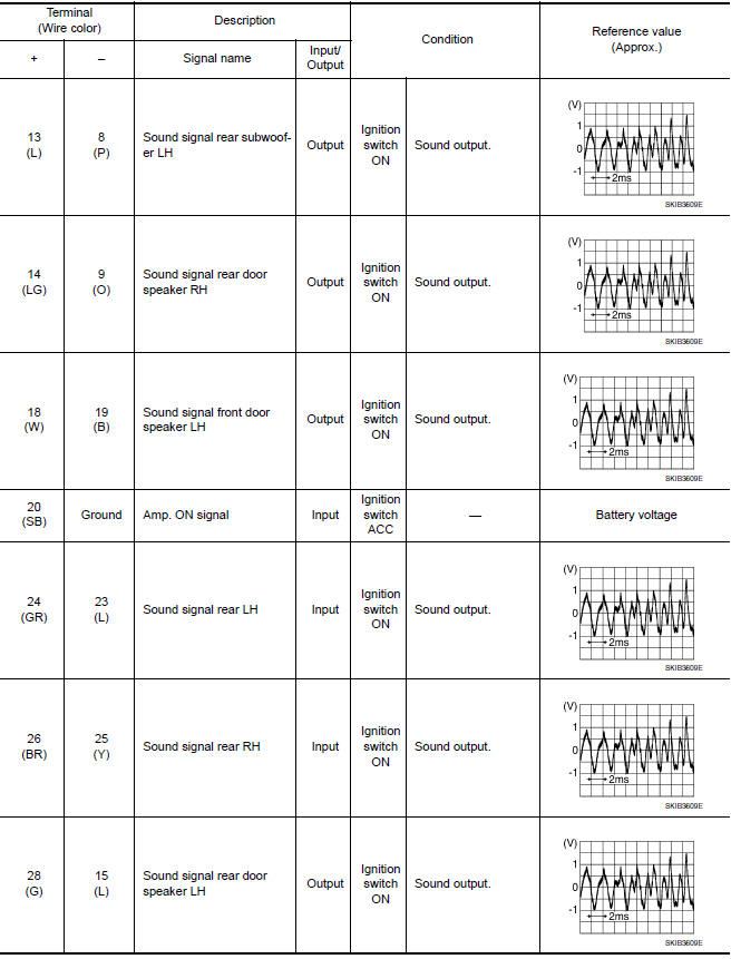
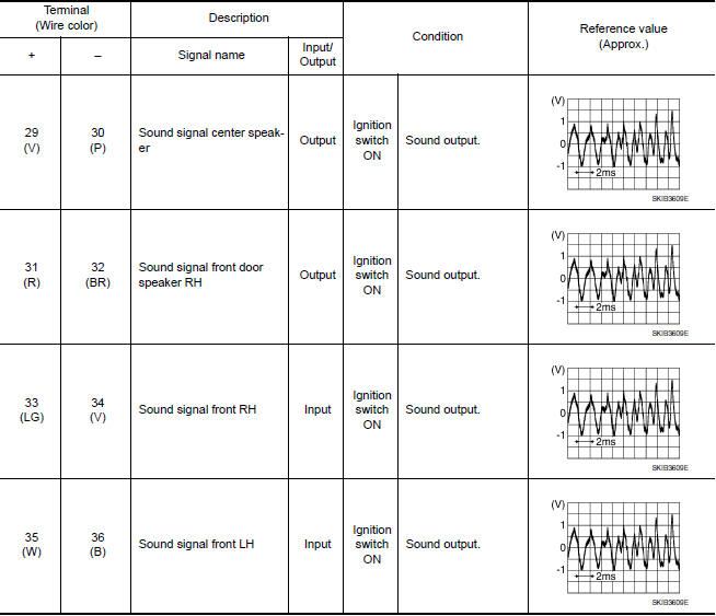
TERMINAL LAYOUT
PHYSICAL VALUES
 Display unit
Reference Values
TERMINAL LAYOUT
PHYSICAL VALUES
...
 Bluetooth control unit
Reference Values
TERMINAL LAYOUT
PHYSICAL VALUES
...
Other materials:
Entry/exit function
This system is designed so that the driver's seat
and automatic operation steering column will automatically
move when the shift lever is in the P
(Park) position. This allows the driver to get into
and out of the driver's seat more easily.
The driver's seat will slide backward and the
steer ...
P0132, P0152 A/F sensor 1
Description
The air fuel ratio (A/F) sensor 1 is a planar one-cell limit current sensor.
The sensor element of the A/F sensor 1 is composed an electrode
layer, which transports ions. It has a heater in the element.
The sensor is capable of precise measurement = 1, but also in the
lean ...
Diagnosis and repair workflow
Work Flow
PRECAUTIONS FOR DIAGNOSIS
If steering angle sensor, steering system parts, suspension system parts, ABS
actuator and electric unit (control
unit) or if wheel alignment has been adjusted, be sure to adjust neutral
position of steering angle sensor
before driving. Refer to BRC-6, & ...
Nissan Maxima Owners Manual
- Illustrated table of contents
- Safety-Seats, seat belts and supplemental restraint system
- Instruments and controls
- Pre-driving checks and adjustments
- Monitor, climate, audio, phone and voice recognition systems
- Starting and driving
- In case of emergency
- Appearance and care
- Do-it-yourself
- Maintenance and schedules
- Technical and consumer information
Nissan Maxima Service and Repair Manual

0.0061