Nissan Maxima Service and Repair Manual: Display unit
Reference Values
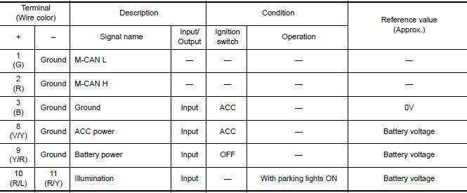
TERMINAL LAYOUT

PHYSICAL VALUES
 Audio unit
Reference Value
TERMINAL LAYOUT
PHYSICAL VALUES
...
 Bose speaker AMP
Reference Values
TERMINAL LAYOUT
PHYSICAL VALUES
...
Other materials:
Relay control system
System Diagram
System Description
IPDM E/R activates the internal control circuit to perform the relay ON-OFF
control according to the input signals
from various sensors and the request signals received from control units via CAN
communication.
CAUTION:
IPDM E/R integrated relays cann ...
P0112, P0113 IAT sensor
Description
The intake air temperature sensor is built-into the mass air flow sensor
(1). The sensor detects intake air temperature and transmits a
signal to the ECM.
The temperature sensing unit uses a thermistor which is sensitive to
the change in temperature. Electrical resistance of ...
Fuel-filler cap
WARNING
Gasoline is extremely flammable and
highly explosive under certain conditions.
You could be burned or seriously
injured if it is misused or mishandled.
Always stop the engine and do not
smoke or allow open flames or sparks
near the vehicle when refueling.
Do not attempt ...
Nissan Maxima Owners Manual
- Illustrated table of contents
- Safety-Seats, seat belts and supplemental restraint system
- Instruments and controls
- Pre-driving checks and adjustments
- Monitor, climate, audio, phone and voice recognition systems
- Starting and driving
- In case of emergency
- Appearance and care
- Do-it-yourself
- Maintenance and schedules
- Technical and consumer information
Nissan Maxima Service and Repair Manual

0.0064