Nissan Maxima Service and Repair Manual: Audio unit
Reference Value
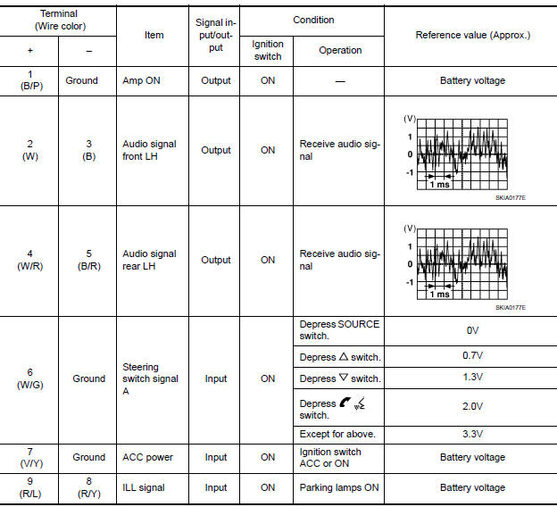
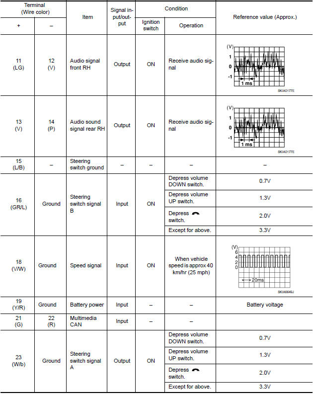
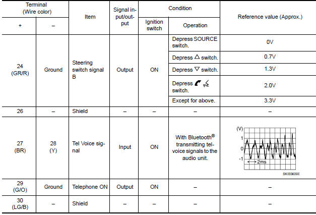
TERMINAL LAYOUT

PHYSICAL VALUES

 Display unit
Reference Values
TERMINAL LAYOUT
PHYSICAL VALUES
...
Other materials:
Precaution
Precaution for Supplemental Restraint System (SRS) "AIR BAG" and "SEAT
BELT
PRE-TENSIONER"
The Supplemental Restraint System such as "AIR BAG" and "SEAT BELT PRE-TENSIONER",
used along
with a front seat belt, helps to reduce the risk or severity of injury to the
driver a ...
Center console assembly
Exploded View
Center console side finisher (LH)
Center console finisher
CVT finisher
Center console storage bin
Center console screw cover (LH)
Center console rear finisher
Center console screw cover (RH)
Center console
Center console lid assembly
Cup holder
Center cons ...
Optical sensor
Exploded View
Optical sensor
LH front tweeter speaker grille
Optical sensor harness connector
LH front tweeter speaker
Instrument panel
Removal and Installation
CAUTION: Whenever a suitable tool is used,
always wrap a cloth around the end of the tool to protect components from ...
Nissan Maxima Owners Manual
- Illustrated table of contents
- Safety-Seats, seat belts and supplemental restraint system
- Instruments and controls
- Pre-driving checks and adjustments
- Monitor, climate, audio, phone and voice recognition systems
- Starting and driving
- In case of emergency
- Appearance and care
- Do-it-yourself
- Maintenance and schedules
- Technical and consumer information
Nissan Maxima Service and Repair Manual

0.0056