Nissan Maxima Service and Repair Manual: AV branch line circuit
Diagnosis Procedure
1.CHECK CONNECTOR
- Turn the ignition switch OFF.
- Disconnect the battery cable from the negative terminal.
- Check the terminals and connectors of the AV control unit for damage, bend and loose connection (unit side and connector side).
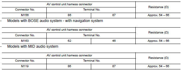
2.CHECK HARNESS FOR OPEN CIRCUIT
- Disconnect the connector of AV control unit.
- Check the resistance between the AV control unit harness connector
terminals.
- Models with BOSE audio system - without navigation system
3.CHECK POWER SUPPLY AND GROUND CIRCUIT
Check the power supply and the ground circuit of the AV control unit. Refer to the following.
- Models without BOSE audio with color display: AV-231, "AV CONTROL UNIT : Diagnosis Procedure"
- Models with BOSE audio with color display: AV-388, "AV CONTROL UNIT : Diagnosis Procedure"
- Models with BOSE audio with color display with navigation system: AV-571, "AV CONTROL UNIT : Diagnosis Procedure"
 M&A branch line circuit
Diagnosis Procedure
1.CHECK CONNECTOR
Turn the ignition switch OFF.
Disconnect the battery cable from the negative terminal.
Check the terminals and connectors of the combination meter for
...
 HVAC branch line circuit
Diagnosis Procedure
1.CHECK CONNECTOR
Turn the ignition switch OFF.
Disconnect the battery cable from the negative terminal.
Check the terminals and connectors of the A/C auto amp. for
dam ...
Other materials:
Front coil spring and strut
Removal and Insallation
REMOVAL
Remove front wheel and tire using power tool. Refer to WT-60,
"Adjustment".
Remove the wheel sensor harness from the front coil spring and
strut. Refer to BRC-102, "Removal and Installation - Front Wheel Sensor".
Remove the brake hose lock plate.
Remo ...
B1150 - B1153 side curtain air bag module LH
Description
DTC B1150 - B1153 LH SIDE CURTAIN AIR BAG MODULE
The LH side curtain air bag module is wired to the air bag diagnosis sensor
unit. The air bag diagnosis sensorunit will monitor for opens and shorts in
detected lines to the LH side curtain air bag module.
PART LOCATION
DTC Logic
...
Periodic maintenance
ROAD WHEEL
Inspection
ALUMINUM WHEEL
Check tires for wear and improper inflation.
Check wheels for deformation, cracks and other damage. If deformed,
remove wheel and check wheel runout.
Remove tire from aluminum wheel and
mount on a tire balance machine. Refer to WT-62, "Rem ...
Nissan Maxima Owners Manual
- Illustrated table of contents
- Safety-Seats, seat belts and supplemental restraint system
- Instruments and controls
- Pre-driving checks and adjustments
- Monitor, climate, audio, phone and voice recognition systems
- Starting and driving
- In case of emergency
- Appearance and care
- Do-it-yourself
- Maintenance and schedules
- Technical and consumer information
Nissan Maxima Service and Repair Manual

0.0062