
Nissan Maxima Service and Repair Manual: Bluetooth control unit
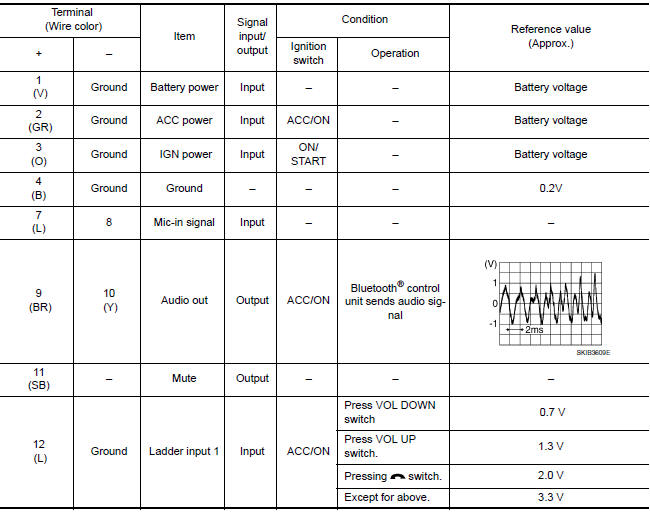
Reference Values
TERMINAL LAYOUT
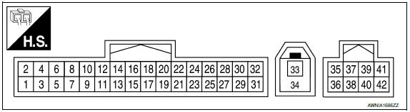
PHYSICAL VALUES
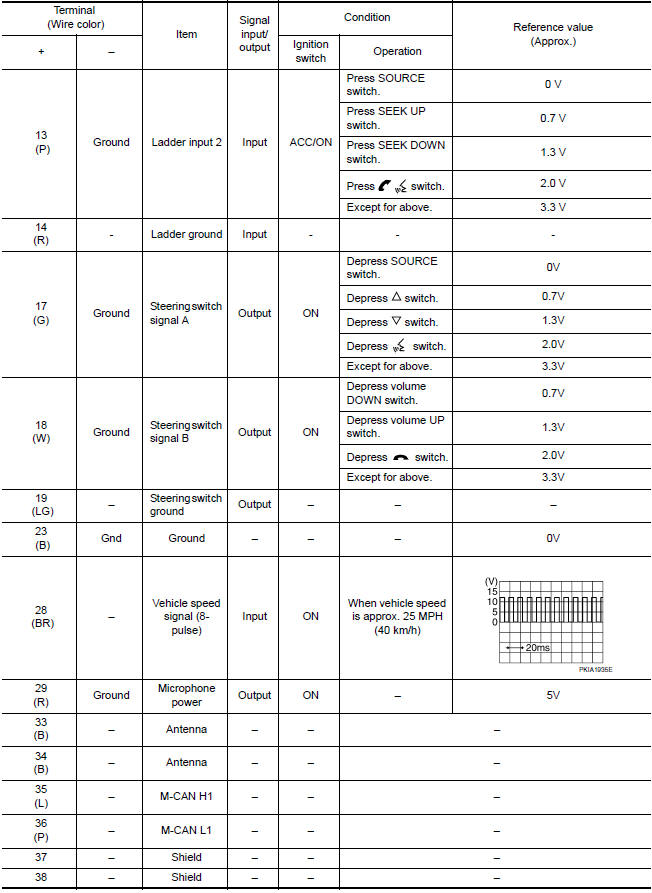
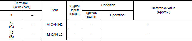
 Bose speaker AMP
Reference Values
TERMINAL LAYOUT
PHYSICAL VALUES
...
 Wiring diagram
MONOCHROME DISPLAY
Wiring Diagram - With BOSE Audio System
...
Other materials:
U1207 AV control unit
DTC Logic
Diagnosis Procedure
1.PERFORM THE SELF-DIAGNOSIS
Delete the "self-diagnosis" results of "MULTI AV". Turn ignition
switch OFF.
Turn ignition switch ON. Perform the self-diagnosis again.
Check that the DTC is detected again.
U1216 AV CONTROL UNIT
DTC Logic
U1217 AV ...
Seat belt maintenance
To clean the seat belt webbing, apply a
mild soap solution or any solution recommended
for cleaning upholstery or carpet.
Then wipe with a cloth and allow the seat
belts to dry in the shade. Do not allow the
seat belts to retract until they are completely
dry.
If dirt builds up in ...
When traveling or registering in another country
When planning to drive your NISSAN vehicle
in another country, you should first find
out if the fuel available is suitable for your vehicle's
engine.
Using fuel with an octane rating that is too low
may cause engine damage. All gasoline vehicles
must be operated with unleaded gasoline. There ...
Nissan Maxima Owners Manual
- Illustrated table of contents
- Safety-Seats, seat belts and supplemental restraint system
- Instruments and controls
- Pre-driving checks and adjustments
- Monitor, climate, audio, phone and voice recognition systems
- Starting and driving
- In case of emergency
- Appearance and care
- Do-it-yourself
- Maintenance and schedules
- Technical and consumer information
Nissan Maxima Service and Repair Manual

0.015