Nissan Maxima Service and Repair Manual: U1000 CAN comm circuit
Description
CAN (Controller Area Network) is a serial communication line for real time application. It is an on-vehicle multiplex communication line with high data communication speed and excellent error detection ability. Many electronic control units are equipped onto a vehicle, and each control unit shares information and links with other control units during operation (not independent). In CAN communication, control units are connected with 2 communication lines (CAN H line, CAN L line) allowing a high rate of information transmission with less wiring.
Each control unit transmits/receives data but selectively reads required data only.
DTC Logic
DTC DETECTION LOGIC
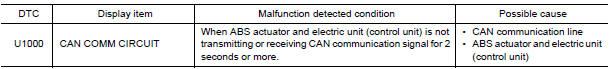
Diagnosis Procedure
1.CHECK CONNECTOR
- Turn ignition switch OFF.
- Disconnect ABS actuator and electric unit (control unit) connector.
- Check terminals for deformation, disconnection, looseness, and so on. If any malfunction is found, repair or replace terminals.
- Reconnect connector and perform self-diagnosis
 C1156 ST ANG sen com cir
Description
The steering angle sensor is connected to the ABS actuator and electric unit
(control unit) in addition to CAN
lines. CAN (Controller Area Network) is a serial communication line for ...
 Parking brake switch
Description
The parking brake switch converts the status of the parking brake pedal to an
electric signal and transmits it to
the combination meter. The combination meter, through CAN communicati ...
Other materials:
Check cooling fan relay
Description
The electrical load signal (Headlamp switch signal, rear window defogger
switch signal, etc.) is transferred via
the CAN communication line from BCM to ECM via the IPDM E/R.
Component Function Check
1.CHECK REAR WINDOW DEFOGGER SWITCH FUNCTION
Turn ignition switch ON.
Connec ...
Power window main switch
Reference Value
TERMINAL LAYOUT
PHYSICAL VALUES
MAIN POWER WINDOW AND DOOR LOCK/UNLOCK SWITCH
Fail Safe
FAIL-SAFE CONTROL
Switches to fail-safe control when malfunction is detected in encoder signal
that detects up/down speed and
direction of door glass. Switches to fail-safe c ...
Optical sensor
Exploded View
Optical sensor
LH front tweeter speaker grille
Optical sensor harness connector
LH front tweeter speaker
Instrument panel
Removal and Installation
CAUTION: Whenever a suitable tool is used,
always wrap a cloth around the end of the tool to protect components from ...
Nissan Maxima Owners Manual
- Illustrated table of contents
- Safety-Seats, seat belts and supplemental restraint system
- Instruments and controls
- Pre-driving checks and adjustments
- Monitor, climate, audio, phone and voice recognition systems
- Starting and driving
- In case of emergency
- Appearance and care
- Do-it-yourself
- Maintenance and schedules
- Technical and consumer information
Nissan Maxima Service and Repair Manual

0.0056