Nissan Maxima Service and Repair Manual: Parking, license plate and tail lamps
System Diagram
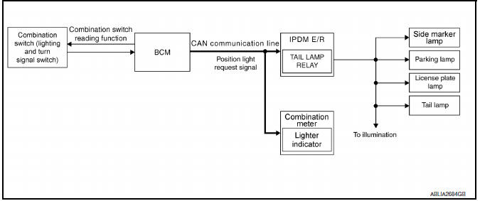
System Description
- BCM (Body Control Module) controls parking, license plate and tail lamps operation.
- IPDM E/R (Intelligent Power Distribution Module Engine Room) operates parking, license plate and tail lamps according to CAN communication signals from BCM.
Component Parts Location
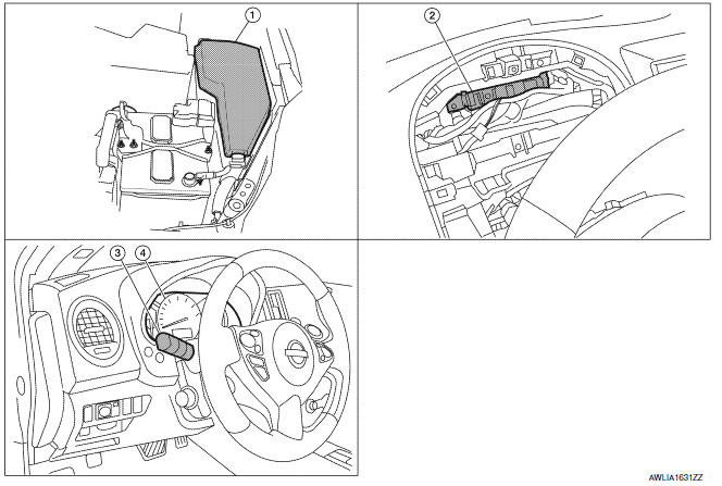
- IPDM E/R E17, E18, E201
- BCM M16, M17, M18, M19 (view with combination meter removed)
- Combination switch (lighting and turn signal switch) M28
- Combination Meter M24
Component Description
PARKING, LICENSE PLATE AND TAIL LAMPS OPERATION
When the lighting switch is in 1ST position, BCM detects the LIGHTING SWITCH 1ST POSITION ON. The BCM sends a parking light ON request through the CAN communication lines to the IPDM E/R. The IPDM E/R then activates the tail lamp relay which sends power to the parking and instrument illumination circuits.
EXTERIOR LAMP BATTERY SAVER CONTROL
With the combination switch (lighting and turn signal switch) in the 2nd position and the ignition switch is turned from ON or ACC to OFF, the battery saver feature is activated.
Under this condition, the headlamps remain illuminated for 5 minutes unless the lighting switch position is changed. If the lighting switch position is changed, then the headlamps are turned off.
This setting can be changed by CONSULT.
 Turn signal and hazard warning lamps
System Diagram
System Description
BCM (Body Control Module) controls turn signal lamp (RH and LH) and
hazard warning lamp operation.
Combination meter operates turn signal indicator (RH an ...
 Combination switch reading system
System Diagram
System Description
OUTLINE
BCM reads the status of the combination switch (light, turn
signal, wiper and washer) and recognizes the status of each switch.
BCM has a combina ...
Other materials:
ABS branch line circuit
Diagnosis Procedure
1.CHECK CONNECTOR
Turn the ignition switch OFF.
Disconnect the battery cable from the negative terminal.
Check the terminals and connectors of the ABS actuator and
electric unit (control unit) for damage, bend
and loose connection (unit side and connector side).
...
Vents
Side
Adjust air flow direction by moving the vent
slides.
Open or close the vents by using the dial. Move
the dial toward the to open
the vents or
toward the to close them.
Center
Rear (center console) ...
Power outlet
Console Box
The power outlet is for powering electrical accessories
such as cellular telephones. It is rated at
12 volt, 120W (10A) maximum.
The power outlet is powered only when the ignition
switch is in the ACC or ON position.
CAUTION
The outlet and plug may be hot during
or immedi ...
Nissan Maxima Owners Manual
- Illustrated table of contents
- Safety-Seats, seat belts and supplemental restraint system
- Instruments and controls
- Pre-driving checks and adjustments
- Monitor, climate, audio, phone and voice recognition systems
- Starting and driving
- In case of emergency
- Appearance and care
- Do-it-yourself
- Maintenance and schedules
- Technical and consumer information
Nissan Maxima Service and Repair Manual

0.0072