Nissan Maxima Service and Repair Manual: Combination switch reading system
System Diagram
System Description
OUTLINE
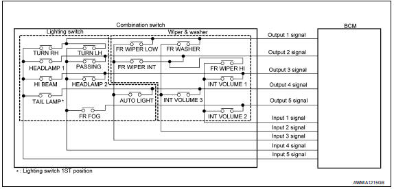
- BCM reads the status of the combination switch (light, turn signal, wiper and washer) and recognizes the status of each switch.
- BCM has a combination of 5 output terminals (OUTPUT 1 - 5) and 5 input terminals (INPUT 1 - 5) and reads a maximum of 20 switch states.
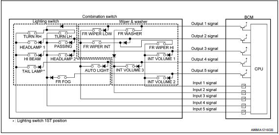
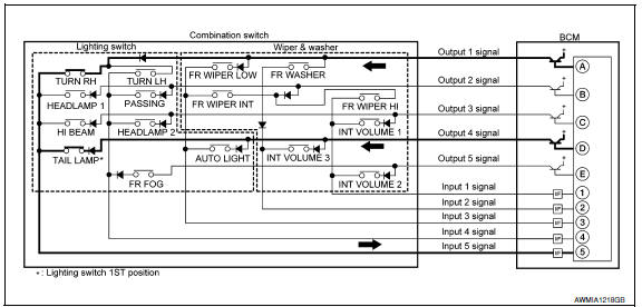
COMBINATION SWITCH MATRIX
Combination switch circuit
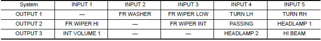
Combination switch INPUT-OUTPUT system list

COMBINATION SWITCH READING FUNCTION
Description
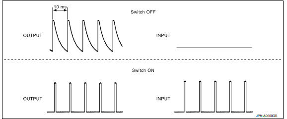
- BCM reads the status of the combination switch at 10ms intervals normally.
NOTE: BCM reads the status of the combination switch at 60ms intervals when BCM is controlled at low power consumption mode.
- BCM operates as follows and judges the status of the combination switch.
- It operates the transistor on OUTPUT side in the following order: OUTPUT 1 → 2 →3 →4 →5 and outputs voltage waveform.
- - The voltage waveform of OUTPUT corresponding to the formed circuit is input into the interface on INPUT side if any (1 or more) switches are ON.
- It reads this change of the voltage as the status signal of the combination switch.
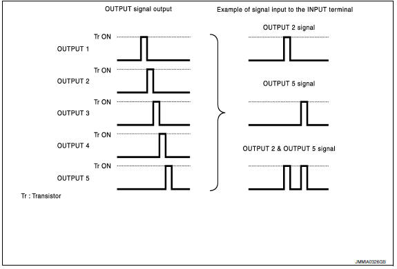
Operation Example
In the following operation example, the combination of the status signals of the combination switch is replaced as follows: INPUT 1 - 5 to "1 - 5" and OUTPUT 1 - 5 to "A - E".
Example 1: When a switch (TAIL LAMP) is turned ON
- The circuit between OUTPUT 4 and INPUT 5 is formed when the TAIL LAMP is turned ON.
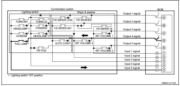
- BCM detects the combination switch status signal "5D" when the signal of OUTPUT 4 is input to INPUT 5
- BCM judges that the TAIL LAMP switch is ON when the signal "5D" is detected.
Example 2: When some switches (TRUN RH, TAIL LAMP) are turned ON
- The circuits between OUTPUT 1 and INPUT 5 and between OUTPUT 4 and INPUT 5 are formed when the TURN RH switch and TAIL LAMP switch are turned ON.
- BCM detects the combination switch status signal "5AD" when the signals of OUTPUT 1 and OUTPUT 4 are input to INPUT 5.
- BCM judges that the TURN RH switch and TAIL LAMP switch are ON when the signal "5AD" is detected.
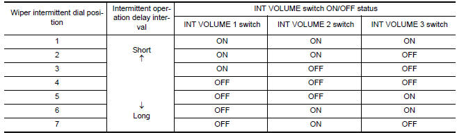
WIPER INTERMITTENT DIAL POSITION SETTING (FRONT WIPER INTERMITTENT OPERATION)
BCM judges the wiper intermittent dial 1 - 7 by the status of INT VOLUME 1, 2, and 3 switches.
 Parking, license plate and tail lamps
System Diagram
System Description
BCM (Body Control Module) controls parking, license plate and tail lamps
operation.
IPDM E/R (Intelligent Power Distribution Module Engine Room) operates ...
 Diagnosis system (BCM)
COMMON ITEM
COMMON ITEM : CONSULT Function (BCM - COMMON ITEM)
APPLICATION ITEM
CONSULT performs the following functions via CAN communication with BCM
SYSTEM APPLICATION
BCM can perform the fo ...
Other materials:
DTC/circuit diagnosis
SUNSHADE
Component Parts Location
Rear sunshade unit B22 (View with the rear parcel shelf finisher
removed)
Rear sunshade switch M308
Reference Value
...
Servicing air conditioner
The air conditioner system in your NISSAN vehicle
is charged with a refrigerant designed with
the environment in mind.
This refrigerant does not harm the earth's
ozone layer.
Special charging equipment and lubricant is required
when servicing your NISSAN air conditioner.
Using improper refr ...
Parking, license plate and tail lamps system
Wiring Diagram
...
Nissan Maxima Owners Manual
- Illustrated table of contents
- Safety-Seats, seat belts and supplemental restraint system
- Instruments and controls
- Pre-driving checks and adjustments
- Monitor, climate, audio, phone and voice recognition systems
- Starting and driving
- In case of emergency
- Appearance and care
- Do-it-yourself
- Maintenance and schedules
- Technical and consumer information
Nissan Maxima Service and Repair Manual

0.0055