Nissan Maxima Service and Repair Manual: Turn signal and hazard warning lamps
System Diagram

System Description
- BCM (Body Control Module) controls turn signal lamp (RH and LH) and hazard warning lamp operation.
- Combination meter operates turn signal indicator (RH and LH) according to CAN communication signals from BCM.
Component Parts Location
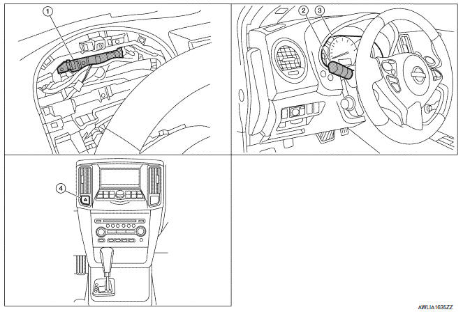
- BCM M16, M17, M18, M19 (view with combination meter removed)
- Combination switch (lighting and turn signal switch) M28
- Combination meter M24
- Hazard switch M54
Component Description
TURN SIGNAL OPERATION
When the turn signal switch is in LH or RH position with the ignition switch in ON position, the BCM detects the TURN RH or TURN LH ON request. The BCM outputs the flasher output signal to the respective turn signal lamp. The BCM sends a turn signal indicator ON request through the CAN communication lines to the combination meter. The combination meter then activates the appropriate turn signal indicator and audible buzzer.
HAZARD LAMP OPERATION
When the hazard switch is in ON position, the BCM detects the hazard switch signal ON. The BCM outputs the flasher output signal (right and left). The BCM sends a hazard indicator signal ON request through the CAN communication lines to the combination meter. The combination meter then activates the hazard indicator and audible buzzer.
REMOTE KEYLESS ENTRY OPERATION
The remote keyless entry receiver transmits Intelligent Key signal to BCM, then BCM controls hazard lamps.
Refer to SEC-19, "System Description".
 Front fog lamp
System Diagram
System Description
BCM (Body Control Module) controls front fog lamp operation.
IPDM E/R (Intelligent Power Distribution Module Engine Room) operates
front fog lamp accordin ...
 Parking, license plate and tail lamps
System Diagram
System Description
BCM (Body Control Module) controls parking, license plate and tail lamps
operation.
IPDM E/R (Intelligent Power Distribution Module Engine Room) operates ...
Other materials:
Key reminder function
System Description
Key reminder is the function that prevents the key from being left in the
vehicle.
Key reminder has the following 3 functions.
Key reminder function
Operation condition
Operation
Driver door closed
Right after driver side door is close ...
Electrical units location
Electrical Units Location
ENGINE COMPARTMENT
PASSENGER COMPARTMENT
LUGGAGE COMPARTMENT
...
Outside key antenna
Description
Detects whether Intelligent Key is outside the vehicle.
Integrated in front outside handle (driver side, passenger side) and installed
in rear bumper.
Component Function Check
NOTE:
The Signal Tech II Tool (J-50190) can be used to perform the following
functions. Refer to t ...
Nissan Maxima Owners Manual
- Illustrated table of contents
- Safety-Seats, seat belts and supplemental restraint system
- Instruments and controls
- Pre-driving checks and adjustments
- Monitor, climate, audio, phone and voice recognition systems
- Starting and driving
- In case of emergency
- Appearance and care
- Do-it-yourself
- Maintenance and schedules
- Technical and consumer information
Nissan Maxima Service and Repair Manual

0.0065