Nissan Maxima Service and Repair Manual: Front fog lamp
System Diagram
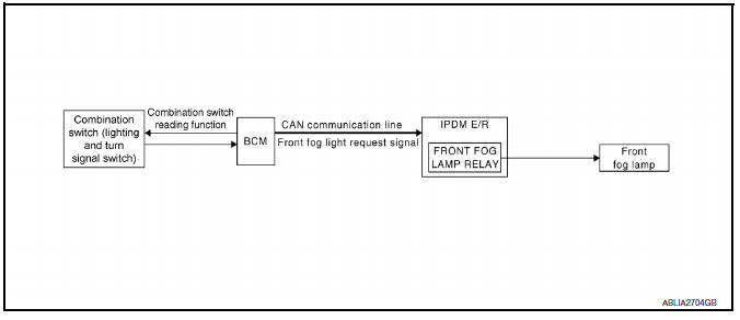
System Description
- BCM (Body Control Module) controls front fog lamp operation.
- IPDM E/R (Intelligent Power Distribution Module Engine Room) operates front fog lamp according to CAN communication signals from BCM.
- Combination meter operates front fog lamp indicator according to inputs via the CAN communication lines.
Component Parts Location
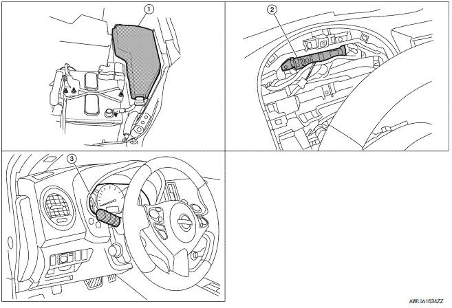
- IPDM E/R E17, E18, E200
- BCM M16, M17, M18, M19 (view with combination meter removed)
- Combination switch (lighting and turn signal switch) M28
Component Description
FRONT FOG LAMP OPERATION
When the lighting switch is in front fog lamp ON position and also in 1ST or 2ND position or AUTO position (headlamp is ON), the BCM detects FR FOG ON and the HEAD LAMP1, 2 ON or the AUTO LIGHT ON. The BCM sends a front fog lamp request ON signal through the CAN communication lines to the IPDM E/R. The IPDM E/R then turns ON the front fog lamp relay sending power to the front fog lamps.
The combination meter also receives a front fog lamp request ON signal through the CAN communication lines at which time it turns the front fog indicator ON.
 Auto light system
System Diagram
System Description
BCM (Body Control Module) controls auto light operation according to
signals from optical sensor, lighting switch and ignition switch.
IPDM E/R (Intellige ...
 Turn signal and hazard warning lamps
System Diagram
System Description
BCM (Body Control Module) controls turn signal lamp (RH and LH) and
hazard warning lamp operation.
Combination meter operates turn signal indicator (RH an ...
Other materials:
Memory function does not operate
Component Function Check
Symptom
Memory function does not operate normally.
The setting is not maintained. (It returns to the initial
condition.)
1.CHECK OPERATION
Set temperature control dial to 32C (90F).
Press the OFF switch.
Turn the ignition switch OFF.
Turn the ignition ...
Difference between predicted and actual distances
The displayed guidelines and their locations on
the ground are for approximate reference only.
Objects on uphill or downhill surfaces or projecting
objects will be actually located at distances
different from those displayed in the monitor relative
to the guidelines (refer to illustrations). ...
Engine speed signal circuit
Description
ECM sends engine speed signal to power steering control unit.
Diagnosis Procedure
1.PERFORM ECM SELF-DIAGNOSIS
With CONSULT
Perform ECM self-diagnosis.
2.CHECK HARNESS BETWEEN ECM AND POWER STEERING CONTROL UNIT FOR OPEN
Turn the ignition switch OFF.
Disconnect ECM connec ...
Nissan Maxima Owners Manual
- Illustrated table of contents
- Safety-Seats, seat belts and supplemental restraint system
- Instruments and controls
- Pre-driving checks and adjustments
- Monitor, climate, audio, phone and voice recognition systems
- Starting and driving
- In case of emergency
- Appearance and care
- Do-it-yourself
- Maintenance and schedules
- Technical and consumer information
Nissan Maxima Service and Repair Manual

0.0066