Nissan Maxima Service and Repair Manual: Auto light system
System Diagram
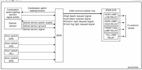
System Description
- BCM (Body Control Module) controls auto light operation according to signals from optical sensor, lighting switch and ignition switch.
- IPDM E/R (Intelligent Power Distribution Module Engine Room) operates parking, license plate, tail, front fog lamps and headlamps according to CAN communication signals from BCM.
- Optical sensor detects ambient brightness of 800 to 2,500 lux, converts light (lux) to voltage, and then sends the optical sensor signal to BCM.
OUTLINE
The auto light control system has an optical sensor that detects outside brightness.
When the lighting switch is in AUTO position, it automatically turns ON/OFF the parking, license plate, tail, front fog lamps and headlamps in accordance with the ambient light. Sensitivity can be adjusted in four steps.
For the details of the setting, refer
Component Parts Location
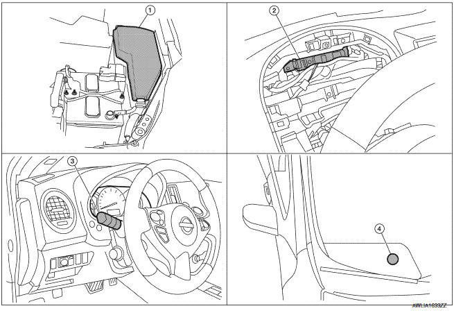
- IPDM E/R E17, E18, E200
- BCM M16, M17, M18, M19, M21 (view with combination meter removed)
- Combination switch (lighting and turn signal switch) M28
- Optical sensor M66
Component Desription
AUTO LIGHT OPERATION
Applicable lamps
- Low beam headlamp
- Parking, license plate and tail lamps
- High beam headlamp (with the lighting switch in HIGH BEAM position)
- Front fog lamp (with the lighting switch in front fog lamp ON position)
When the lighting switch is in AUTO position with the ignition switch in ON position, BCM detects the AUTO LIGHT (ON) by BCM combination switch (lighting and turn signal switch) reading function. BCM automatically turns ON/OFF the applicable lamps according to ambient brightness. NOTE: Timing for when lamps turn ON/OFF can be changed by the function setting of CONSULT.
 Daytime running light system
System Diagram
System Description
The headlamp system for Canada vehicles is equipped with a daytime light
relay that activates the high beam headlamps at approximately half
illumination whene ...
 Front fog lamp
System Diagram
System Description
BCM (Body Control Module) controls front fog lamp operation.
IPDM E/R (Intelligent Power Distribution Module Engine Room) operates
front fog lamp accordin ...
Other materials:
Rear power window switch
Removal and Installation
REMOVAL
Remove the rear door armrest finisher. Refer to INT-21,
"Removal and Installation".
Release the pawls on each side to separate the switch finisher
(1) from the rear power window switch (2) using a suitable tool
(A).
: Pawl
INSTALLA ...
Main line between DLC and HVAC circuit
Diagnosis Procedure
1.CHECK HARNESS CONTINUITY (OPEN CIRCUIT)
Turn the ignition switch OFF.
Disconnect the battery cable from the negative terminal.
Disconnect the following harness connectors.
ECM
A/C auto amp.
Check the continuity between the data link connector and the A/C ...
Side air bag (satellite) sensor
Removal and Installation
CAUTION:
Before servicing, turn ignition switch OFF, disconnect both
battery terminals and wait at least 3 minutes.
Do not use air tools or electric tools for servicing.
Replace the satellite sensor of deployed SRS front side air
bag and deployed SRS side ...
Nissan Maxima Owners Manual
- Illustrated table of contents
- Safety-Seats, seat belts and supplemental restraint system
- Instruments and controls
- Pre-driving checks and adjustments
- Monitor, climate, audio, phone and voice recognition systems
- Starting and driving
- In case of emergency
- Appearance and care
- Do-it-yourself
- Maintenance and schedules
- Technical and consumer information
Nissan Maxima Service and Repair Manual

0.0059