
Nissan Maxima Service and Repair Manual: Hands-free phone system
System Diagram
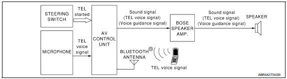
System Description
Refer to the Owner's Manual for Bluetooth telephone system operating instructions.
NOTE: Cellular telephones must have their wireless connection set up (paired) before using the Bluetooth telephone system.
Bluetooth telephone system allows users who have a Bluetooth equipped cellular telephone to make a wireless connection between their cellular telephone and the AV control unit. Hands-free cellular telephone calls can be sent and received. Personal memos can be created using the Nissan Voice Recognition system.
Some Bluetooth cellular telephones may not be recognized by the AV control unit. When a cellular telephone or the AV control unit is replaced, the telephone must be paired with the AV control unit. Different cellular telephones may have different pairing procedures. Refer to the cellular telephone operating manual and the vehicle Owner's Manual for more information.
AV CONTROL UNIT
When the ignition switch is turned to ACC or ON, the AV control unit will power up. During power up, the Bluetooth feature is initialized and performs various self-checks. Initialization may take up to 10 seconds. If a phone is present in the vehicle and paired with the AV control unit, Nissan Voice Recognition will then become active. Bluetooth telephone functions can be turned off using the Nissan Voice Recognition system.
STEERING WHEEL AUDIO CONTROL SWITCHES
When buttons on the steering wheel audio control switch are pushed, the resistance in steering wheel audio control switch circuit changes depending on which button is pushed. The AV control unit uses this signal to perform various functions while navigating through the voice recognition system.
The following functions can be performed using the steering wheel audio control switch:
- Initiate self-diagnosis of the Bluetooth telephone system
- Start a voice recognition session
- Answer and end telephone calls
- Adjust the volume of calls
- Record memos
MICROPHONE
The microphone is located in the roof console assembly. The microphone sends a signal to the AV control unit.
The microphone can be actively tested during self-diagnosis.
Component Parts Location
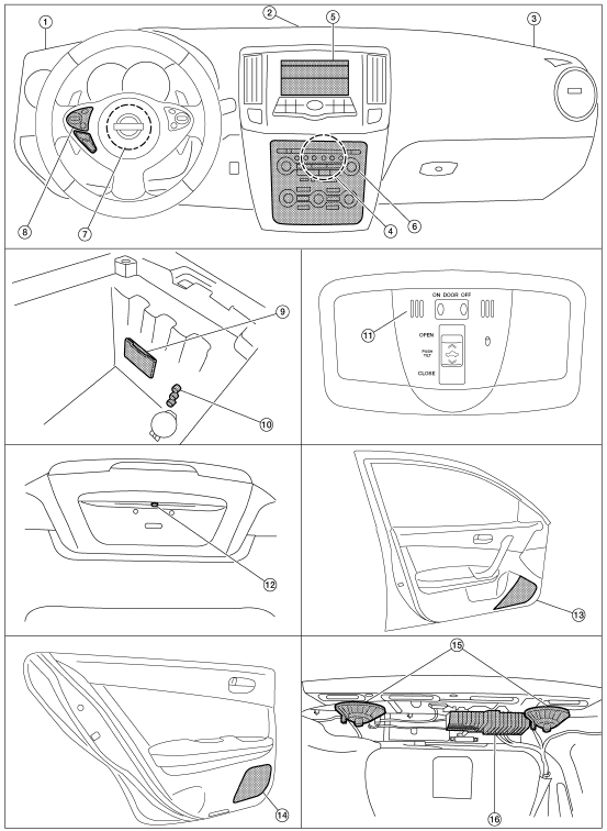
- Tweeter LH M51
- Center speaker M130
- Tweeter RH M52
- AV control unit M160, M161, M162, M163, M164, M165, M166, M167, M168 (located behind A/C and AV switch assembly)
- Display unit M142, M151
- A/C and AV switch assembly M98
- Steering angle sensor M53 [located in steering column behind combination switch (spiral cable)]
- Steering wheel audio control switches
- USB interface M211(view in center console)
- Aux in jack M209
- Microphone R7
- Rear view camera T101
- Front door speaker
LH D3
RH D103 - Rear door speaker
LH D202
RH D302 - Rear subwoofers (view under rear
parcel shelf)
LH B106
RH B107 - BOSE speaker amp B109, B110
Component Description
|
Part name |
Description |
| AV control unit |
|
| BOSE speaker amp |
|
| Front door speaker | Receives telephone voice and voice guidance signals from the AV control unit through the BOSE speaker amp. |
| Front tweeter | |
| Center speaker | |
| Steering wheel audio control switches |
|
| Microphone | Sends voice signals to AV control unit |
| Bluetooth antenna | Sends telephone voice signal to AV control unit |
 Rear view monitor system
System Diagram
System Description
When the shift selector is in the R position, the display unit shows a view
to the rear of the vehicle. Lines which
indicate the vehicle clearance and dista ...
 Diagnosis system (AV control unit)
Description
The AV control unit diagnosis function starts up with multifunction
switch operation and the AV control unit
performs a diagnosis for each unit in the system during the on board ...
Other materials:
Bluetooth control unit
Reference Value
TERMINAL LAYOUT
PHYSICAL VALUES
...
Optical sensor
Description
The optical sensor converts the outside brightness (lux) to voltage and
transmits the optical sensor signal to the BCM.
Component Function Check
1.CHECK OPTICAL SENSOR SIGNAL BY CONSULT
CONSULT
Turn the ignition switch ON.
Select "OPTICAL SENSOR" of BCM (HEAD LAMP) DATA MONIT ...
Combination meter
Removal and Installation
REMOVAL
Disconnect the negative battery terminal. Refer
to PG-67, "Removal and Installation (Battery)".
Remove the cluster lid A. Refer to IP-16,
"Removal and Installation".
Remove the combination meter screws (A) using
powe ...
Nissan Maxima Owners Manual
- Illustrated table of contents
- Safety-Seats, seat belts and supplemental restraint system
- Instruments and controls
- Pre-driving checks and adjustments
- Monitor, climate, audio, phone and voice recognition systems
- Starting and driving
- In case of emergency
- Appearance and care
- Do-it-yourself
- Maintenance and schedules
- Technical and consumer information
Nissan Maxima Service and Repair Manual

0.0088