Nissan Maxima Service and Repair Manual: Rear view monitor system
System Diagram
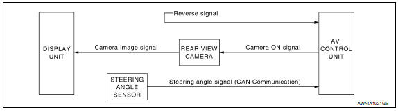
System Description
When the shift selector is in the R position, the display unit shows a view to the rear of the vehicle. Lines which indicate the vehicle clearance and distances are also displayed.
Component Parts Location
- Tweeter LH M51
- Center speaker M130
- Tweeter RH M52
- AV control unit M160, M161, M162, M163, M164, M165, M166, M167, M168 (located behind A/C and AV switch assembly)
- Display unit M142, M151
- A/C and AV switch assembly M98
- Steering angle sensor M53 [located in steering column behind combination switch (spiral cable)]
- Steering wheel audio control switches
- USB interface M211(view in center console)
- Aux in jack M209
- Microphone R7
- Rear view camera T101
- Front door speaker
LH D3
RH D103 - Rear door speaker
LH D202
RH D302 - Rear subwoofers (view under rear
parcel shelf)
LH B106
RH B107 - BOSE speaker amp B109, B110
Component Description
|
Part name |
Description |
| AV control unit |
|
| Rear view camera |
|
| Steering angle sensor | Sends steering angle information to the AV control unit via CAN communication |
 Navigation system
System Diagram
System Description
NOTE:
Refer to NAVI System Owner's Manual for system operation.
The navigation system periodically calculates the vehicle's current position
accor ...
 Hands-free phone system
System Diagram
System Description
Refer to the Owner's Manual for Bluetooth telephone system operating
instructions.
NOTE:
Cellular telephones must have their wireless connection set up ...
Other materials:
Door outside molding
Exploded View
Front door sash molding
Front door outside molding
Rear door outside molding
Rear door sash molding (lower)
Rear door sash molding (upper)
Pawl
Removal and Installation
FRONT DOOR OUTSIDE MOLDING
Removal
Open the front door window fully.
Remove the ...
Turning the FEB system on/off
Perform the following steps to turn the FEB systems
ON or OFF.
1. Press the button until
"Settings" displays
in the vehicle information display and
then press OK button. Use the
button
to select "Driver Assistance". Then press the
OK button.
2. Select "Emergency Brake" ...
Door request switch
Description
Transmits door lock/unlock operation to BCM.
Component Function Check
1. CHECK FUNCTION
With CONSULT
Check door request switch REQ SW-DR, REQ SW-AS in Data Monitor mode.
Diagnosis Procedure
1. CHECK DOOR REQUEST SWITCH OUTPUT SIGNAL
Turn ignition switch OFF.
Check ...
Nissan Maxima Owners Manual
- Illustrated table of contents
- Safety-Seats, seat belts and supplemental restraint system
- Instruments and controls
- Pre-driving checks and adjustments
- Monitor, climate, audio, phone and voice recognition systems
- Starting and driving
- In case of emergency
- Appearance and care
- Do-it-yourself
- Maintenance and schedules
- Technical and consumer information
Nissan Maxima Service and Repair Manual

0.0053