Nissan Maxima Service and Repair Manual: Front stabilizer
Removal and Installation
REMOVAL
- Remove the steering gear and linkage. Refer to ST-26, "Removal and Installation".
- Remove the nuts on the upper portion of stabilizer connecting rod
- Remove the stabilizer clamp bolts.
- Remove the front stabilizer from the vehicle
INSPECTION AFTER REMOVAL
Check the front stabilizer, the stabilizer connecting rod, the stabilizer bushing, and the stabilizer clamp for deformation, cracks and damage. Replace if necessary.
INSTALLATION
Installation is in the reverse order of removal. Refer to FSU-13, "Exploded View".
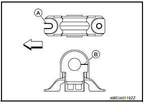
- When installing stabilizer, make sure that notch (A) in stabilizer clips face front.
- Make sure each slit (B) in the surface of each stabilizer bushing faces the rear of the vehicle.
- : Front.
- The front stabilizer uses a pillow ball type stabilizer connecting rod.
Position the ball joint with the case on the pillow ball head parallel to the front stabilizer.
 Transverse link
Removal and Installation
REMOVAL
Remove front wheel and tire using power tool. Refer to WT-60,
"Adjustment".
Remove the knuckle spindle bolt and nut at the transverse link.
Remove the stee ...
 Steering knuckle
Removal and Installation
Steering knuckle
Splash guard
Wheel hub and bearing
Cotter pin
REMOVAL
Remove the front wheel hub and bearing. Refer to FAX-7, "Removal
and Installat ...
Other materials:
Navigation system
System Diagram
System Description
NOTE:
Refer to NAVI System Owner's Manual for system operation.
The navigation system periodically calculates the vehicle's current position
according to the following three
signals: Travel distance of the vehicle as determined by the vehicle s ...
Checking lights
Anti-lock Braking System (ABS)
warning light
Brake warning light (parking brake)
Brake warning light
Charge warning light
Engine oil pressure warning light
Forward Emergency Braking (FEB) system warning
light (if so eq ...
Parking, license plate and tail lamps system
Wiring Diagram
...
Nissan Maxima Owners Manual
- Illustrated table of contents
- Safety-Seats, seat belts and supplemental restraint system
- Instruments and controls
- Pre-driving checks and adjustments
- Monitor, climate, audio, phone and voice recognition systems
- Starting and driving
- In case of emergency
- Appearance and care
- Do-it-yourself
- Maintenance and schedules
- Technical and consumer information
Nissan Maxima Service and Repair Manual

0.0057