Nissan Maxima Service and Repair Manual: Front fog lamp
System Diagram
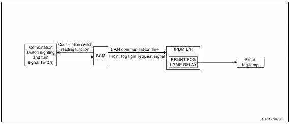
System Description
- BCM (Body Control Module) controls front fog lamp operation.
- IPDM E/R (Intelligent Power Distribution Module Engine Room) operates front fog lamp according to CAN communication signals from BCM.
- Combination meter operates front fog lamp indicator according to inputs via the CAN communication lines.
Component Parts Location
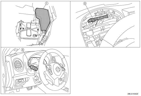
- IPDM E/R E17, E18, E200
- BCM M16, M17, M18, M19 (view with combination meter removed)
- Combination switch (lighting and turn signal switch) M28
Component Description
FRONT FOG LAMP OPERATION
When the lighting switch is in front fog lamp ON position and also in 1ST or 2ND position or AUTO position (headlamp is ON), the BCM detects FR FOG ON and the HEAD LAMP1, 2 ON or the AUTO LIGHT ON. The BCM sends a front fog lamp request ON signal through the CAN communication lines to the IPDM E/R. The IPDM E/R then turns ON the front fog lamp relay sending power to the front fog lamps.
The combination meter also receives a front fog lamp request ON signal through the CAN communication lines at which time it turns the front fog indicator ON.
 Auto light system
System Diagram
System Description
BCM (Body Control Module) controls auto light operation according to
signals from optical sensor, lighting switch and ignition switch.
IPDM E/R (Intellige ...
 Turn signal and hazard warning lamps
System Diagram
System Description
BCM (Body Control Module) controls turn signal lamp (RH and LH) and
hazard warning lamp operation
Combination meter operates turn signal indicator (RH and ...
Other materials:
Text Messaging
Using the Bluetooth Hands-Free Phone System,
a received text message can be operated on
the vehicle information display as well as on the
touch-screen display.
To read/ignore an incoming text
1. When a new text message is received, a
pop-up window and operation keys will appear
with the sende ...
Moving Object Detection (MOD) (if so equipped)
1. CAMERA button
WARNING
Failure to follow the warnings and instructions
for proper use of the Moving
Object Detection system could result in
serious injury or death.
The MOD system is not a substitute for
proper vehicle operation and is not designed
to prevent contact with obje ...
C1142 press sen circuit
Description
The pressure sensor converts the brake fluid pressure to an electric signal
and transmits it to the ABS actuator
and electric unit (control unit). (The pressure sensor is integrated in the ABS
actuator and electric unit (control
unit).)
DTC Logic
DTC DETECTION LOGIC
DTC C ...
Nissan Maxima Owners Manual
- Illustrated table of contents
- Safety-Seats, seat belts and supplemental restraint system
- Instruments and controls
- Pre-driving checks and adjustments
- Monitor, climate, audio, phone and voice recognition systems
- Starting and driving
- In case of emergency
- Appearance and care
- Do-it-yourself
- Maintenance and schedules
- Technical and consumer information
Nissan Maxima Service and Repair Manual

0.0054