Nissan Maxima Service and Repair Manual: U1243 display unit
Description
| Part name | Description |
| DISPLAY UNIT |
|
DTC Logic
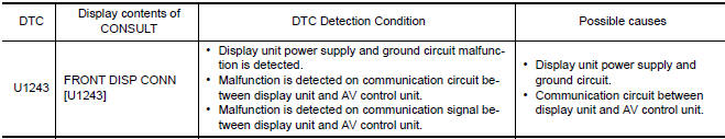
Diagnosis Procedure
1.CHECK DISPLAY UNIT POWER SUPPLY AND GROUND CIRCUIT
Check display unit power supply and ground circuit
2.CHECK CONTINUITY OF COMMUNICATION CIRCUIT
- Turn ignition switch OFF.
- Disconnect display unit connector and AV control unit connector.
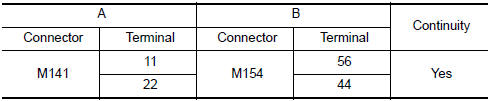
- Check continuity between display unit harness connector M141 (A) terminals 11, 22 and AV control unit harness connector M154 (B) terminals 56, 44.
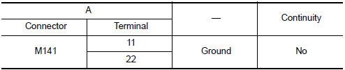
- Check continuity between display unit harness connector M141 (A) terminals 11, 22 and ground.
3.CHECK COMMUNICATION SIGNAL
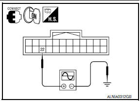
- Connect display unit connector and AV control unit connector.
- Turn ignition switch ON.
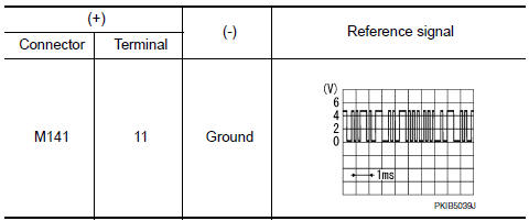
- Check signal between display unit harness connector M141 terminal 11 and ground with an oscilloscope or CONSULT.
4.CHECK COMMUNICATION SIGNAL
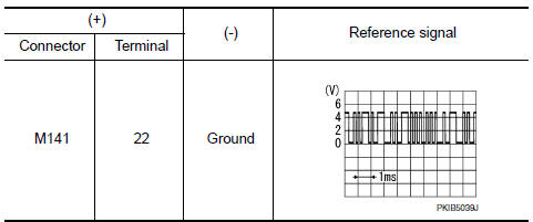
Check signal between display unit harness connector M141 terminal 22 and ground with an oscilloscope or CONSULT.
 U1232 steering angle sensor
DTC Logic
Diagnosis Procedure
ADJUST THE PREDICTIVE COURSE LINE CENTER POSITION OF THE STEERING ANGLE
SENSOR
When U1232 is detected, adjust the predictive course line center position of
the s ...
 U1263 USB
DTC Logic
Diagnosis Procedure
1.CHECK USB HARNESS
Visually check USB harness. ...
Other materials:
B257B, B257C ambient sensor
Description
COMPONENT DESCRIPTION
Ambient Sensor
The ambient sensor (1) is installed to the front bumper
reinforcement.
It detects ambient temperature and converts it into a resistance
value which is then input into the A/C auto amp.
Ambient Sensor Circuit
AMBIENT TEMPERATUR ...
Inside mirror
Wiring Diagram - Without Homelink Universal Transceiver
Wiring Diagram - With Homelink Universal Transceiver
...
Automatic speed control device (ASCD)
System Diagram
System Description
INPUT/OUTPUT SIGNAL CHART
*: This signal is sent to the ECM via the CAN communication line
BASIC ASCD SYSTEM
Refer to Owner's Manual for ASCD operating instructions.
Automatic Speed Control Device (ASCD) allows a driver to keep vehicle at
predeterm ...
Nissan Maxima Owners Manual
- Illustrated table of contents
- Safety-Seats, seat belts and supplemental restraint system
- Instruments and controls
- Pre-driving checks and adjustments
- Monitor, climate, audio, phone and voice recognition systems
- Starting and driving
- In case of emergency
- Appearance and care
- Do-it-yourself
- Maintenance and schedules
- Technical and consumer information
Nissan Maxima Service and Repair Manual

0.0063