
Nissan Maxima Service and Repair Manual: AV branch line circuit
Diagnosis Procedure
1.CHECK CONNECTOR
- Turn the ignition switch OFF.
- Disconnect the battery cable from the negative terminal.
- Check the terminals and connectors of the AV control unit for damage, bend and loose connection (unit side and connector side).
2.CHECK HARNESS FOR OPEN CIRCUIT
- Disconnect the connector of AV control unit.
- Check the resistance between the AV control unit harness connector
terminals.
- Models with BOSE audio system - without navigation system
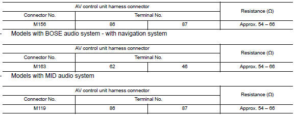
3.CHECK POWER SUPPLY AND GROUND CIRCUIT
Check the power supply and the ground circuit of the AV control unit. Refer to the following.
- Models without BOSE audio with color display: AV-231, "AV CONTROL UNIT : Diagnosis Procedure"
- Models with BOSE audio with color display: AV-388, "AV CONTROL UNIT : Diagnosis Procedure"
- Models with BOSE audio with color display with navigation system: AV-571, "AV CONTROL UNIT : Diagnosis Procedure"
 M&A branch line circuit
Diagnosis Procedure
1.CHECK CONNECTOR
Turn the ignition switch OFF.
Disconnect the battery cable from the negative terminal.
Check the terminals and connectors of the combination meter for
...
 HVAC branch line circuit
Diagnosis Procedure
1.CHECK CONNECTOR
Turn the ignition switch OFF.
Disconnect the battery cable from the negative terminal.
Check the terminals and connectors of the A/C auto amp. for
dam ...
Other materials:
Headlining
Exploded View
Rear assist grip
Front assist grip
Front room/map lamp assembly (dual panel- sunroof)
Sun visor (RH)
Sun visor (LH)
Mirror harness cover
Sun visor cover
Front room/map lamp assembly
Sun visor holder
Rear assist grip LH
Headlining assembly (single panel s ...
Spark Plug
Exploded View
Ignition coil
Spark plug
Rocker cover (RH)
Rocker cover (LH)
Removal and Installation
REMOVAL
Remove the ignition coil. Refer to EM-42, "Removal and
Installation (LH)" and EM-42, "Removal and Installation (RH)".
Remove the spark plug with a suitable spark p ...
Vertical synchronizing (VP) signal circuit
Description
In composite image (AUX image, camera image), transmit the vertical
synchronizing (VP) signal and horizontal
synchronizing (HP) signal from display unit to AV control unit so as to
synchronize the RGB images displayed
with AV control unit, such as the image quality adjusting men ...
Nissan Maxima Owners Manual
- Illustrated table of contents
- Safety-Seats, seat belts and supplemental restraint system
- Instruments and controls
- Pre-driving checks and adjustments
- Monitor, climate, audio, phone and voice recognition systems
- Starting and driving
- In case of emergency
- Appearance and care
- Do-it-yourself
- Maintenance and schedules
- Technical and consumer information
Nissan Maxima Service and Repair Manual

0.0074