Nissan Maxima Service and Repair Manual: DLC branch line circuit
Diagnosis Procedure
1.CHECK CONNECTOR
-
Turn the ignition switch OFF.
-
Disconnect the battery cable from the negative terminal.
-
Check the terminals and connectors of the data link connector for damage, bend and loose connection (connector side and harness side).
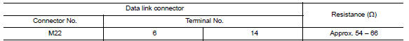
2.CHECK HARNESS FOR OPEN CIRCUIT
Check the resistance between the data link connector terminals.
 BCM branch line circuit
Diagnosis Procedure
1.CHECK CONNECTOR
Turn the ignition switch OFF.
Disconnect the battery cable from the negative
terminal.
Check the terminals and connec ...
 M&A branch line circuit
Diagnosis Procedure
1.CHECK CONNECTOR
Turn the ignition switch OFF.
Disconnect the battery cable from the negative terminal.
Check the terminals and connectors of the combination meter for
...
Other materials:
P1715 input speed sensor
Description
ECM receives input speed sensor signal from TCM via the CAN communication
line. ECM uses this signal for
engine control.
DTC Logic
DTC DETECTION LOGIC
NOTE:
If DTC P1715 is displayed with DTC UXXXX first perform the
trouble diagnosis for DTC UXXXX. Refer
to EC-161 ...
Unit disassembly and assembly
FRONT DRIVE SHAFT
Disassembly and Assembly (LH)
Circlip
Dust shield
Housing
Snap ring
Spider assembly
Stopper ring
Boot band
Boot
Shaft
Damper band
Dynamic damper
Circlip
. Joint sub-assembly : Wheel side
: Fill us ...
Headlight control switch
Lighting
Rotate the switch to the
position, and
the front parking, tail, license plate, and instrument
panel lights will come on.
Rotate the switch to the
position, and
the headlights will come on and all the other
lights remain on.
CAUTION
Use the headlights with the e ...
Nissan Maxima Owners Manual
- Illustrated table of contents
- Safety-Seats, seat belts and supplemental restraint system
- Instruments and controls
- Pre-driving checks and adjustments
- Monitor, climate, audio, phone and voice recognition systems
- Starting and driving
- In case of emergency
- Appearance and care
- Do-it-yourself
- Maintenance and schedules
- Technical and consumer information
Nissan Maxima Service and Repair Manual

0.0065