Nissan Maxima Service and Repair Manual: Water outlet and water piping
Removal and Installation
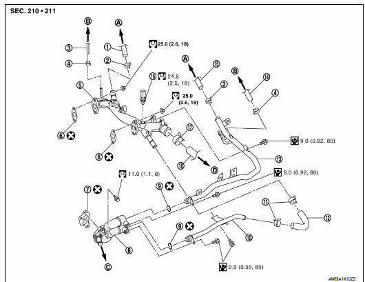
- Heater hose
- Clamp
- Water hose
- Clamp
- Water outlet
- Gasket
- Gasket
- Water connector
- O-ring
- Water bypass pipe
- Clamp
- Water hose
- Heater pipe
- Water hose
- Heater hose
- Engine coolant temperature sensor
- Clamp
- Radiator hose (upper)
- To heater core
- To electric throttle control actuator
- To oil cooler
- To radiator
WARNING: Do not remove the radiator cap when the engine is hot. Serious burns could occur from high pressure engine coolant escaping from the radiator. Wrap a thick cloth around the radiator cap. Slowly turn it a quarter of a turn to release built-up pressure. Carefully remove radiator cap by turning it all the way.
NOTE: When removing components such as hoses, tubes/lines, etc., cap or plug openings to prevent fluid from spilling.
REMOVAL
CAUTION: Perform when the engine is cold.
- Partially drain coolant from radiator. Refer to CO-11, "Changing Engine Coolant".
- Remove engine room cover. Refer to EM-23, "Removal and Installation"
- Remove front air duct and air cleaner case assembly. Refer to EM-24, "Removal and Installation".
- Disconnect electric throttle control actuator coolant hoses.
- Remove radiator hose (upper) and both heater hoses.
- Remove connector(s) from heater pipe.
- Remove engine coolant temperature sensor on water outlet.
- Remove water outlet, heater pipe, water connector, and water bypass pipe nuts and bolts
INSTALLATION
- Installation is in the reverse order of removal.
- Securely insert each hose, and install a clamp at a position where
it does not interfere with the pipe
bulge.
CAUTION: Do not reuse gasket. - When inserting heater pipe and water bypass pipe into water
connector, apply neutral detergent to new
O-rings.
CAUTION: Do not reuse O-rings. - After installation refill engine coolant and check for leaks. Refer to CO-11, "Changing Engine Coolant" and CO-10, "System Inspection".
 Thermostat and thermostat housing
Removal and Installation
Gasket
Thermostat assembly (water inlet)
WARNING:
Do not remove the radiator cap when the engine is hot. Serious burns could occur
from high pressure
engine ...
 Unit disassembly and assembly
COOLING FAN
Disassembly and Assembly of Cooling Fan
Fan blade
Fan shroud
Fan motor
DISASSEMBLY
Remove fan blade nut.
Remove fan blade from fan motor.
Remove fan motor bolts a ...
Other materials:
High-mounted stop lamp
Exploded View
High-mounted stop lamp cover
High-mounted stop lamp bulb
Removal and Installation
REMOVAL
Slide the high-mounted stop lamp rearward on the parcel shelf to
give clearance to the front locking tabs.
Lift the front of the high-mounted stop lamp up and slide it forward ...
Reclining motor
Description
The reclining motor is installed to the seatback assembly.
The reclining motor is activated with the driver seat control unit.
The seatback is reclined forward/backward by changing the rotation
direction of reclining motor.
Component Function Check
1. CHECK FUNCTION
Se ...
U1000 CAN comm circuit
Description
DTC Logic
DTC DETECTION LOGIC
NOTE:
U1000 can be set if a module harness was disconnected and reconnected, perhaps
during a repair. Confirm
that there are actual CAN diagnostic symptoms and a present DTC by performing
the Self Diagnostic Result
procedure.
Diagnosis Proc ...
Nissan Maxima Owners Manual
- Illustrated table of contents
- Safety-Seats, seat belts and supplemental restraint system
- Instruments and controls
- Pre-driving checks and adjustments
- Monitor, climate, audio, phone and voice recognition systems
- Starting and driving
- In case of emergency
- Appearance and care
- Do-it-yourself
- Maintenance and schedules
- Technical and consumer information
Nissan Maxima Service and Repair Manual

0.0062