
Nissan Maxima Service and Repair Manual: Front disc brake
Disassembly and Assembly
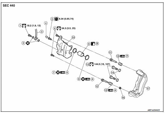
- Union bolt
- Copper sealing washer
- Brake hose
- Cap
- Bleed valve
- Sliding pin bolt
- Piston seal
- Piston
- Piston boot
- Cylinder body
- Upper sliding pin
- Lower sliding pin bolt
- Torque member bolt
- Washer
- Sliding pin boot
- Bushing
- Torque member
- Rubber grease
- Brake fluid
NOTE: Do not remove the torque member, pads, shims, shim covers, and anti-rattle clips when disassembling and assembling the cylinder body.
DISASSEMBLY
- Remove the sliding pin bolts, and then remove the cylinder body
from the torque member.
CAUTION: Do not drop pads, shims, shim cover and anti-rattle clips from torque member. - Remove the sliding pins, bushing and sliding pin boots from the torque member.
- Remove the cap and the bleed valve from the cylinder body.
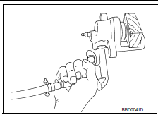
- Place a wooden block in the cylinder body and blow air through
the union bolt hole to push out the piston and piston boot as
shown. Discard the piston boot.
WARNING:
Do not get fingers caught between the piston and cylinder
body.
CAUTION: Do not reuse the piston boot.
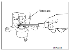
- Remove the piston seal from the cylinder body using a suitable tool as shown. Discard the piston seal.
CAUTION:
- Be careful not to damage the inner cylinder wall.
- Do not reuse the piston seal.
INSPECTION AFTER DISASSEMBLY
Cylinder Body
Check the inner cylinder wall for corrosion, wear, and damage. If a defect is detected, replace the cylinder body.
CAUTION: Clean the cylinder body using new brake fluid. Do not use mineral oils such as gasoline or kerosene.
Torque Member
Check the torque member for wear, cracks, and damage. If a defect is detected, replace the torque member.
Piston
Check the piston surface for corrosion, wear, and damage. If a defect is detected, replace the piston.
CAUTION: The piston sliding surface is plated. Do not polish the piston with sandpaper.
Sliding Pin, Sliding Pin Bolt, and Sliding Pin Boot
Check the sliding pin, sliding pin bolt, and sliding pin boot for wear, damage, and cracks. If a defect is detected, replace the components as necessary.
ASSEMBLY
- Apply rubber grease to the new piston seal, and install it in the cylinder body.
CAUTION: Do not reuse piston seal.
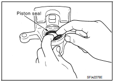
- Apply rubber grease to new piston boot and apply brake fluid to
the piston. Cover the piston end with the piston boot, and then
install the cylinder side lip on the piston boot securely into a
groove on the cylinder body.
CAUTION: Do not reuse piston boot.
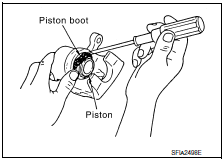
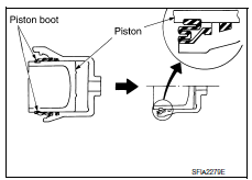
- Push the piston into the cylinder body by hand and push the piston
boot piston-side lip into the piston groove.
CAUTION: Press the piston evenly and vary the pressing point to prevent cylinder inner wall from being rubbed.
- Install the bleed valve and cap to the cylinder body.
- Install the sliding pins, bushing and sliding pin boots on the torque member.
- Install the cylinder body to the torque member, and then tighten the sliding pin bolts to the specified torque.

 Rear disc brake
Disassembly and Assembly
Union bolt
Brake hose
Copper sealing washer
Cap
Bleed valve
Lower sliding pin bolt
Upper sliding pin bolt
Bushing
Cylinder body
Piston seal
P ...
Other materials:
RGB area (YS) signal circuit
Description
Transmits the display area of RGB image displayed by AV control unit with RGB
area (YS) signal to display
unit.
Diagnosis Procedure
1.CHECK CONTINUITY RGB AREA (YS) SIGNAL CIRCUIT
Turn ignition switch OFF.
Disconnect display unit connector M141 and AV control unit
con ...
ECM branch line circuit
Diagnosis Procedure
1.CHECK CONNECTOR
Turn the ignition switch OFF.
Disconnect the battery cable from the negative terminal.
Check the following terminals and connectors for damage, bend and
loose connection (unit side and connector
side).
- Models without automatic drive positione ...
Precautions
PRECAUTION
Precaution for Supplemental Restraint System (SRS) "AIR BAG" and
"SEAT BELT PRE-TENSIONER "
The Supplemental Restraint System such as "AIR BAG" and "SEAT BELT PRE-TENSIONER
",
used along
with a front seat belt, helps to reduce the risk or ...
Nissan Maxima Owners Manual
- Illustrated table of contents
- Safety-Seats, seat belts and supplemental restraint system
- Instruments and controls
- Pre-driving checks and adjustments
- Monitor, climate, audio, phone and voice recognition systems
- Starting and driving
- In case of emergency
- Appearance and care
- Do-it-yourself
- Maintenance and schedules
- Technical and consumer information
Nissan Maxima Service and Repair Manual

0.0125