Nissan Maxima Service and Repair Manual: M&A branch line circuit
Diagnosis Procedure
1.CHECK CONNECTOR
- Turn the ignition switch OFF.
- Disconnect the battery cable from the negative terminal.
- Check the terminals and connectors of the combination meter for damage, bend and loose connection (unit side and connector side).
2.CHECK HARNESS FOR OPEN CIRCUIT
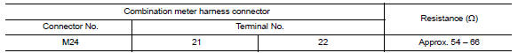
- Disconnect the connector of combination meter.
- Check the resistance between the combination meter harness connector terminals.
3.CHECK POWER SUPPLY AND GROUND CIRCUIT
Check the power supply and the ground circuit of the combination meter. Refer to MWI-37, "COMBINATION METER : Diagnosis Procedure".
 DLC branch line circuit
Diagnosis Procedure
1.CHECK CONNECTOR
Turn the ignition switch OFF.
Disconnect the battery cable from the negative terminal.
Check the terminals and connectors of the data link connector for ...
 AV branch line circuit
Diagnosis Procedure
1.CHECK CONNECTOR
Turn the ignition switch OFF.
Disconnect the battery cable from the negative terminal.
Check the terminals and connectors of the AV control unit for
d ...
Other materials:
Diagnosis and repair workflow
Work Flow
OVERALL SEQUENCE
DETAILED FLOW
1.CHECK SYMPTOM
Check the malfunction symptoms by performing the following items.
Interview the customer to obtain the malfunction information (conditions
and environment when the malfunction
occurred).
Check the symptom.
2.SELF-DIAGNOS ...
Tilt &telescopic switch ground circuit
Diagnosis Procedure
1. CHECK ADP STEERING SWITCH (TILT & TELESCOPIC SWITCH) GROUND CIRCUIT
Turn ignition switch OFF.
Disconnect ADP steering switch (tilt & telescopic switch).
Check continuity between ADP steering switch (tilt & telescopic
switch) and ground.
...
Service data and specifications (SDS)
Idle Speed
Ignition Timing
Calculated Load Value
Mass Air Flow Sensor
*: Engine is warmed up to normal operating temperature and running under no
load. ...
Nissan Maxima Owners Manual
- Illustrated table of contents
- Safety-Seats, seat belts and supplemental restraint system
- Instruments and controls
- Pre-driving checks and adjustments
- Monitor, climate, audio, phone and voice recognition systems
- Starting and driving
- In case of emergency
- Appearance and care
- Do-it-yourself
- Maintenance and schedules
- Technical and consumer information
Nissan Maxima Service and Repair Manual

0.0063