Nissan Maxima Service and Repair Manual: DLC branch line circuit
Diagnosis Procedure
1.CHECK CONNECTOR
- Turn the ignition switch OFF.
- Disconnect the battery cable from the negative terminal.
- Check the terminals and connectors of the data link connector for damage, bend and loose connection (connector side and harness side).
2.CHECK HARNESS FOR OPEN CIRCUIT
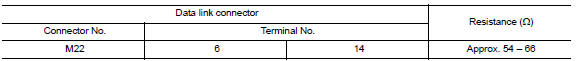
Check the resistance between the data link connector terminals.
 BCM branch line circuit
Diagnosis Procedure
1.CHECK CONNECTOR
Turn the ignition switch OFF.
Disconnect the battery cable from the negative terminal.
Check the terminals and connectors of the BCM for damage, bend and ...
 M&A branch line circuit
Diagnosis Procedure
1.CHECK CONNECTOR
Turn the ignition switch OFF.
Disconnect the battery cable from the negative terminal.
Check the terminals and connectors of the combination meter for
...
Other materials:
Diagnosis system (BCM)
COMMON ITEM
COMMON ITEM: CONSULT Function (BCM - COMMON ITEM)
APPLICATION ITEM
CONSULT performs the following functions via CAN communication with BCM.
Direct Diagnostic Mode
Description
Ecu Identification
The BCM part number is displayed
Self Diagnostic Re ...
B terminal circuit
Description
"B" terminal circuit supplies power to charge the battery and operate the
vehicle's electrical system.
Diagnosis Procedure
1.CHECK "B" TERMINAL CONNECTION
Turn ignition switch OFF.
Check if "B" terminal is clean and tight
2.CHECK "B" TERMINAL CIRCUIT
Check voltage between ...
Difference between predicted and actual distances
The displayed guidelines and their locations on
the ground are for approximate reference only.
Objects on uphill or downhill surfaces or projecting
objects will be actually located at distances
different from those displayed in the monitor relative
to the guidelines (refer to illustrations). ...
Nissan Maxima Owners Manual
- Illustrated table of contents
- Safety-Seats, seat belts and supplemental restraint system
- Instruments and controls
- Pre-driving checks and adjustments
- Monitor, climate, audio, phone and voice recognition systems
- Starting and driving
- In case of emergency
- Appearance and care
- Do-it-yourself
- Maintenance and schedules
- Technical and consumer information
Nissan Maxima Service and Repair Manual

0.0057