Nissan Maxima Service and Repair Manual: Headlamp aiming adjustment
Description
PREPARATION BEFORE ADJUSTING
CAUTION: Do not use organic solvent (thinner, gasoline etc.)
NOTE:
- For details, refer to the regulations in your own country.
- Perform aiming adjustment if the vehicle front body has been repaired and/or the front combination lamp assembly has been replaced.
Before performing aiming adjustment, check the following.
- Keep all tires inflated to correct pressure.
- Place vehicle on level ground.
- See that the vehicle is unloaded (except for full levels of coolant, engine oil and fuel, and spare tire, jack, and tools). Have the driver or equivalent weight placed in drivers seat.
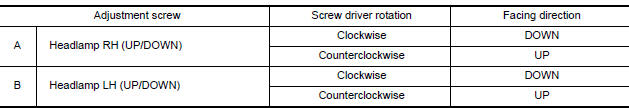
AIMING ADJUSTMENT SCREW
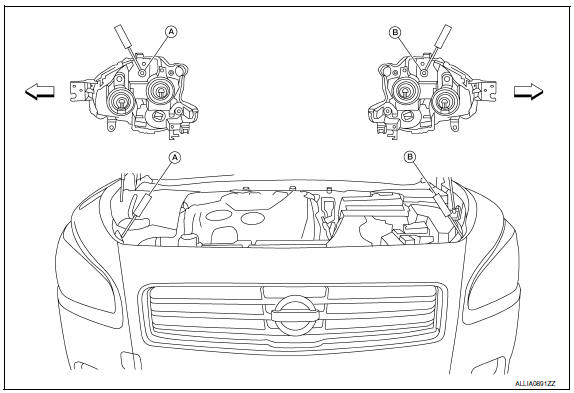
- Headlamp RH (UP/DOWN) adjustment screw
- Headlamp LH (UP/DOWN) adjustment screw
 Vehicle center
Aiming Adjustment Procedure
NOTE: Set the screen so that it is perpendicular to the road.
- Position the screen.
- Make the distance between the headlamp center and the screen 7.62 m (25 ft.).
- Start the engine and illuminate the headlamp (LO). CAUTION: Do not cover the lens surface with tape, etc. because it is made of plastic. NOTE: Block the light from the headlamp that is not being adjusted with a thick fabric or similar object, so that it does not reach the screen.
- Use the adjustment screw to adjust the low beams on the screen, so that it is within the aiming adjustment area.
Adjustment Using An Adjustment Screen (Light/Dark Borderline)
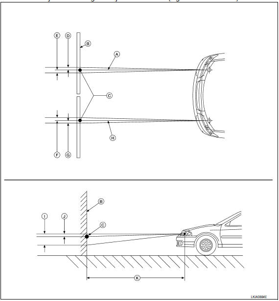
- Headlamp beam (RH)
- Screen
- Horizontal/Vertical center point of headlamp
- 66.5 mm (2.6 in)
- 66.5 mm (2.6 in)
- 66.5 mm (2.6 in)
- 66.5 mm (2.6 in)
- Headlamp beam (LH)
- 53.2 mm (2.1 in)
- 13.3 mm (0.5 in)
- 7.62 m (25 ft)

 Front fog lamp aiming adjustment
Description
PREPARATION BEFORE ADJUSTING
CAUTION: Do not use organic solvent
(thinner, gasoline etc.).
NOTE: For
details, refer to the regulations in your own country.
Before performing
aimi ...
Other materials:
PFCW system limitations
Illustration A
Illustration B
WARNING
Listed below are the system limitations for
the PFCW system. Failure to operate the
vehicle in accordance with these system
limitations could result in serious injury or
death.
The PFCW system cannot detect all vehicles
under all conditions.
Th ...
P0078, P0084 EVT control magnet retarder
Description
Exhaust valve timing control magnet retarder (1) controls the shut/
open timing of the exhaust valve by ON/OFF pulse duty signals sent
from the ECM.
The longer pulse width retards valve timing.
The shorter pulse width advances valve timing.
DTC Logic
DTC DETECTION LOGIC
...
Rear view camera
Removal and Installation
REMOVAL
Remove the license plate finisher. Refer to EXL-166, "Removal and
Installation".
Remove trunk lid finisher. Refer to INT-36, "Exploded View".
Disconnect the rear view camera connector (B), press the rear
view camera tab (A) and remove the rear view c ...
Nissan Maxima Owners Manual
- Illustrated table of contents
- Safety-Seats, seat belts and supplemental restraint system
- Instruments and controls
- Pre-driving checks and adjustments
- Monitor, climate, audio, phone and voice recognition systems
- Starting and driving
- In case of emergency
- Appearance and care
- Do-it-yourself
- Maintenance and schedules
- Technical and consumer information
Nissan Maxima Service and Repair Manual

0.0058