Nissan Maxima Service and Repair Manual: Front fog lamp aiming adjustment
Description
PREPARATION BEFORE ADJUSTING
CAUTION: Do not use organic solvent (thinner, gasoline etc.).
NOTE: For details, refer to the regulations in your own country.
Before performing aiming adjustment, check the following.
- Keep all tires inflated to correct pressure.
- Place vehicle on level ground.
- See that the vehicle is unloaded (except for full levels of coolant, engine oil and fuel, and spare tire, jack, and tools). Have the driver or equivalent weight placed in drivers seat.
AIMING ADJUSTMENT SCREW
- Turn the aiming adjusting screw for adjustment as shown.
NOTE: A screwdriver or hexagonal wrench [6 mm (0.24 in)] can be used for adjustment.
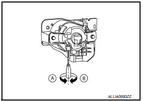
- A: Up
- B: Down
Aiming Adjustment Procedur
NOTE: Set the screen so that it is perpendicular to the road.
- Position the screen.
- Make the distance between the headlamp center and the screen 7.62 m (25 ft.).
- Start the engine and illuminate the fog lamp ON.
CAUTION: Do not cover the lens surface with tape, etc. because it is made of plastic.
NOTE: Block the light from the headlamp that is not being adjusted with a thick fabric or similar object, so that it does not reach the screen
- Adjust the cutoff line height (A) with the aiming adjustment screw so that the distance (X) between the horizontal center line of front fog lamp (H) and (A) becomes 100 mm (4.0 in).
- Front fog lamp light distribution on the screen is as shown.
- A: Cutoff line
- B: High illuminance area
- H: Horizontal center line of front fog lamp
- V: Vertical center line of front fog lamp
- X: Cutoff line height
 Headlamp aiming adjustment
Description
PREPARATION BEFORE ADJUSTING
CAUTION: Do not use organic solvent
(thinner, gasoline etc.)
NOTE:
For details, refer to the regulations in your own country.
Perform aiming adjustm ...

Other materials:
P0605 ECM
Description
The ECM consists of a microcomputer and connectors for signal
input and output and for power supply. The ECM controls the engine
DTC Logic
DTC DETECTION LOGIC
DTC CONFIRMATION PROCEDURE
1.PRECONDITIONING
If DTC Confirmation Procedure has been previously conducted, always ...
Washer switch
Description
Washer switch is integrated with combination switch (wiper and washer
switch).
Combination switch (wiper and washer switch) supplies ground and fuse #
38 from the IPEM E/R suppliespower for the front washer motor to
operate.
Component Inspection
1. CHECK WASHER SWITC ...
Steering switch
Removal and Installation
REMOVAL
Remove the driver airbag module. Refer to SR-12, "Removal and
Installation".
Remove the steering wheel audio control switch screws (A).
Release the steering wheel audio control switch harness clips
(B).
Remove the steering wheel audio contr ...
Nissan Maxima Owners Manual
- Illustrated table of contents
- Safety-Seats, seat belts and supplemental restraint system
- Instruments and controls
- Pre-driving checks and adjustments
- Monitor, climate, audio, phone and voice recognition systems
- Starting and driving
- In case of emergency
- Appearance and care
- Do-it-yourself
- Maintenance and schedules
- Technical and consumer information
Nissan Maxima Service and Repair Manual

0.0084