Nissan Maxima Service and Repair Manual: Door lock actuator
DRIVER SIDE
DRIVER SIDE : Description
Locks/unlocks the door with the signal from BCM.
DRIVER SIDE : Component Function Check
1. CHECK FUNCTION
- Use CONSULT to perform Active Test ("DOOR LOCK").
- Touch "ALL LOCK" or "ALL UNLOCK" to check that it works normally.
DRIVER SIDE : Diagnosis Procedure
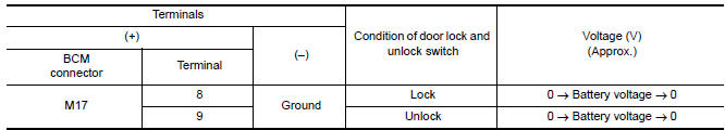
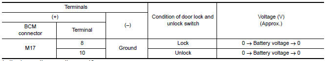
1. CHECK OUTPUT SIGNAL
Check voltage between BCM connector and ground
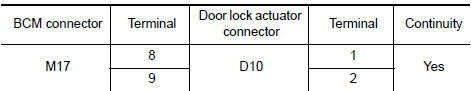
2. CHECK DOOR LOCK ACTUATOR CIRCUIT
- Turn ignition switch OFF.
- Disconnect BCM and front door lock actuator driver side connector.
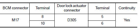
- Check continuity between BCM connector and front door lock actuator driver side connector.
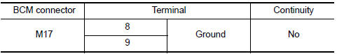
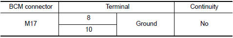
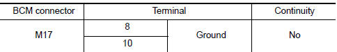
- Check continuity between BCM connector and ground.
3. CHECK INTERMITTENT INCIDENT
PASSENGER SIDE
PASSENGER SIDE : Description
Locks/unlocks the door with the signal from BCM.
PASSENGER SIDE : Component Function Check
1. CHECK FUNCTION
- Use CONSULT to perform Active Test ("DOOR LOCK").
- Touch "ALL LOCK" or "ALL UNLOCK" to check that it works normally.
PASSENGER SIDE : Diagnosis Procedure
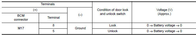
1. CHECK DOOR LOCK ACTUATOR SIGNAL
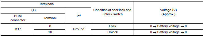
Check voltage between BCM connector and ground.
2. CHECK DOOR LOCK ACTUATOR CIRCUIT
- Turn ignition switch OFF.
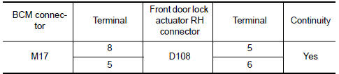
- Disconnect BCM and front door lock actuator RH connectors.
- Check continuity between BCM connector and front door lock actuator RH.
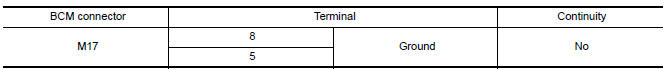
- Check continuity between BCM connector and ground
3. CHECK INTERMITTENT INCIDENT
REAR LH
REAR LH : Description
Locks/unlocks the door with the signal from BCM.
REAR LH : Component Function Check
1. CHECK FUNCTION
- Use CONSULT to perform Active Test ("DOOR LOCK").
- Touch "ALL LOCK" or "ALL UNLOCK" to check that it works normally.
REAR LH : Diagnosis Procedure
1. CHECK DOOR LOCK ACTUATOR SIGNAL
Check voltage between BCM connector and ground
2. CHECK DOOR LOCK ACTUATOR CIRCUIT
- Turn ignition switch OFF.
- Disconnect BCM and rear door lock actuator LH connectors.
- Check continuity between BCM connector and rear door lock actuator LH connectors.
- Check continuity between BCM connector and ground
3. CHECK INTERMITTENT INCIDENT
REAR RH
REAR RH : Description
Locks/unlocks the door with the signal from BCM.
REAR RH : Component Function Check
1. CHECK FUNCTION
- Use CONSULT to perform Active Test ("DOOR LOCK").
- Touch "ALL LOCK" or "ALL UNLOCK" to check that it works normally.
REAR RH : Diagnosis Procedure
1. CHECK DOOR LOCK ACTUATOR SIGNAL
Check voltage between BCM connector and ground.
2. CHECK DOOR LOCK ACTUATOR CIRCUIT
- Turn ignition switch OFF.
- Disconnect BCM and rear door lock actuator RH connectors.
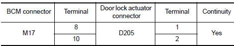
- Check continuity between BCM connector and rear door lock actuator RH connectors.
- Check continuity between BCM connector and ground.
3. CHECK INTERMITTENT INCIDENT
FUEL FILLER LID LOCK ACTUATOR
FUEL FILLER LID LOCK ACTUATOR : Description
Locks/unlocks the door with the signal from BCM.
FUEL FILLER LID LOCK ACTUATOR : Component Function Check
1. CHECK FUNCTION
- Use CONSULT to perform Active Test ("DOOR LOCK").
- Touch "ALL LOCK" or "ALL UNLOCK" to check that it works normally.
FUEL FILLER LID LOCK ACTUATOR : Diagnosis Procedure
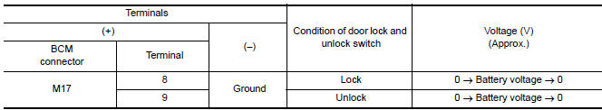
1. CHECK OUTPUT SIGNAL
Check voltage between BCM connector and ground.
2. CHECK FUEL LID DOOR LOCK ACTUATOR CIRCUIT
- Turn ignition switch OFF.
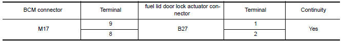
- Disconnect BCM and fuel lid door lock actuator connector.
- Check continuity between BCM connector and fuel lid door lock actuator connector.
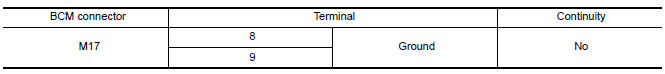
- Check continuity between BCM connector and ground.
3. CHECK INTERMITTENT INCIDENT
 Trunk opener request switch
Description
Performs trunk lid open request when it is pressed.
Component Function Check
1. CHECK FUNCTION
With CONSULT
Check trunk opener request switch REQ SW -BD/TR in Data Monitor mode.
...
 Trunk release solenoid
Description
Performs trunk lid open with signal from BCM.
Component Function Check
1. CHECK TRUNK LID OPENER CANCEL SWITCH
Check trunk lid opener cancel switch position.
2. CHECK FUNCTION
P ...
Other materials:
RearView Monitor system limitations
WARNING
Listed below are the system limitations for
RearView Monitor. Failure to operate the
vehicle in accordance with these system
limitations could result in serious injury or
death.
The system cannot completely eliminate
blind spots and may not show every
object.
Underneath the bu ...
B2614 ACC relay circuit
Description
BCM controls the various electrical components and simultaneously supplies
power according to the power
supply position.
BCM checks the power supply position internally.
DTC Logic
DTC DETECTION LOGIC
DTC CONFIRMATION PROCEDURE
1. PERFORM DTC CONFIRMATION PROCEDURE
Tur ...
B1134 - B1137 side airbag module LH
Description
DTC B1134 - B1137 FRONT LH SIDE AIR BAG MODULE
The front LH side air bag module is wired to the air bag diagnosis sensor
unit. The air bag diagnosis sensorunit will monitor for opens and shorts in
detected lines to the front LH side air bag module.
PART LOCATION
DTC Logic
DTC DE ...
Nissan Maxima Owners Manual
- Illustrated table of contents
- Safety-Seats, seat belts and supplemental restraint system
- Instruments and controls
- Pre-driving checks and adjustments
- Monitor, climate, audio, phone and voice recognition systems
- Starting and driving
- In case of emergency
- Appearance and care
- Do-it-yourself
- Maintenance and schedules
- Technical and consumer information
Nissan Maxima Service and Repair Manual

0.0056