Nissan Maxima Service and Repair Manual: B2614 ACC relay circuit
Description
BCM controls the various electrical components and simultaneously supplies power according to the power supply position.
BCM checks the power supply position internally.
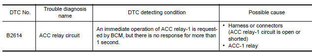
DTC Logic
DTC DETECTION LOGIC
DTC CONFIRMATION PROCEDURE
1. PERFORM DTC CONFIRMATION PROCEDURE
- Turn the power supply position to ACC under the following conditions, and wait for at least 1 second.
- CVT selector lever is in the P or N position.
- Release the brake pedal.
- Check "Self diagnostic result" with CONSULT.
Diagnosis Procedure
1. CHECK ACCESSORY RELAY-1 POWER SUPPLY
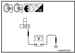
- Turn ignition switch OFF.
- Disconnect accessory relay-1.
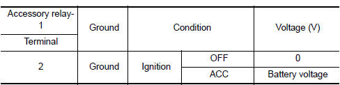
- Check voltage between accessory relay-1 harness connector and ground under the following conditions
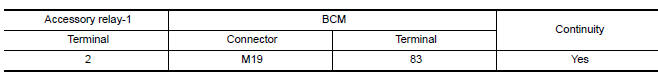
2. CHECK ACCESSORY RELAY-1 POWER SUPPLY CIRCUIT-1
- Turn ignition switch OFF.
- Disconnect BCM harness connector.
- Check continuity between accessory relay-1 harness connector and BCM harness connector.
- Check continuity between accessory relay-1 harness connector and ground.

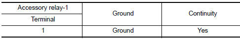
3. CHECK ACCESSORY RELAY-1 GROUND CIRCUIT
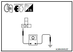
- Turn ignition switch OFF.
- Check continuity between accessory relay-1 harness connector and ground.
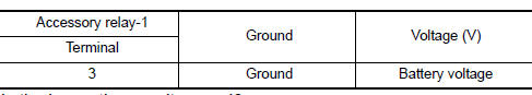
4. CHECK ACCESSORY RELAY-1 POWER SUPPLY CIRCUIT-2
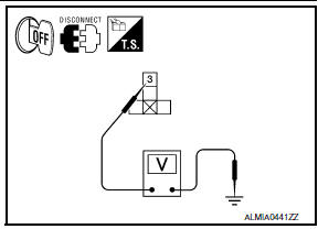
Check voltage between accessory relay-1 harness connector and ground.
5. CHECK ACCESSORY RELAY-1
6. CHECK INTERMITTENT INCIDENT
Component Inspection (Accessory Relay-1)
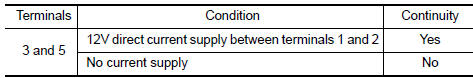
1. CHECK ACCESSORY RELAY-1

- Turn ignition switch OFF.
- Remove accessory relay-1.
- Check the continuity between accessory relay-1 terminals under the following conditions.
 B260A ignition relay
Description
BCM turns ON the following relays to ignition power supply to each ECU when
the ignition switch is turned
ON.
Ignition relay-1 (inside IPDM E/R)
Ignition relay-2 (inside fuse bl ...
 B2615 front blower motor relay circuit
Description
BCM controls the various electrical components and simultaneously supplies
power according to the power
supply position.
BCM checks the power supply position internally.
DTC Logic ...
Other materials:
P0075, P0081 IVT control solenoid valve
Description
Intake valve timing control solenoid valve is activated by ON/OFF
pulse duty (ratio) signals from the ECM.
The intake valve timing control solenoid valve changes the oil
amount and direction of flow via the intake valve timing control unit
or stops oil flow.
The longer p ...
Front combination lamp
Exploded View
Front combination lamp
Removal and Installation
FRONT COMBINATION LAMP
Removal
CAUTION: Disconnect the battery negative terminal or
remove the fuse.
Remove the front bumper fascia. Refer to EXT-16, "Removal and
Installation".
Remove the front ...
Shift lock release
If the battery charge is low or discharged, the
shift lever may not be moved from the P (Park)
position even with the brake pedal depressed
and the shift lever button pressed.
It will be necessary to jump start or have your
battery charged, For additional information, refer
to "Jump star ...
Nissan Maxima Owners Manual
- Illustrated table of contents
- Safety-Seats, seat belts and supplemental restraint system
- Instruments and controls
- Pre-driving checks and adjustments
- Monitor, climate, audio, phone and voice recognition systems
- Starting and driving
- In case of emergency
- Appearance and care
- Do-it-yourself
- Maintenance and schedules
- Technical and consumer information
Nissan Maxima Service and Repair Manual

0.0051