Nissan Maxima Owners Manual: Memory Storage Function (Key-Link)
Use the following process to setup key-link: 1. Unlock the vehicle with the desired Intelligent Key while the ignition is OFF.
2. Place the ignition in the ON position.
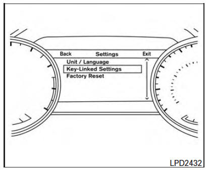
3. Within the "Settings" menu of the vehicle information display, select "Key-Linked Settings" and press the OK button on the steering switch.
4. While in the menu, press the OK button on the steering switch to turn the system ON/OFF.
Once step 4 is completed, every time the ignition is switched from ON to OFF, the memory positions of the driver's seat, automatic steering wheel and the outside mirrors are linked to the Intelligent Key.
Follow the same procedure if you want to link the 2nd, 3rd or 4th Intelligent Key.
NOTE:
If new memory positions are set prior to turning the ignition from ON to OFF, the previously linked memory positions for the respective key will be overwritten by new positions.
Recalling Intelligent Key Memory Positions
If the "Key-Linked Settings" are enabled in the vehicle information display for that particular key, every time you enter the vehicle the driver's seat, automatic steering wheel, and outside mirrors will automatically move to the driver's last position of the respective Intelligent Key.
NOTE:
The key-linked memory positions can be different from the positions stored in the memory switch (1 or 2).
 Automatic drive positioner (if so equipped)
The automatic drive positioner system has three
features:
Memory storage function (Key-link)
Memory storage function (Switch)
Entry/exit function
Key-link, when enabled, automatically reta ...
 Memory storage function
Two positions for the driver's seat, steering column
(if so equipped), and outside mirrors can be stored
in the automatic drive positioner memory. Follow
these procedures to use the memory syst ...
Other materials:
Refrigerant pressure sensor
Removal and Installation
REMOVAL
Discharge the refrigerant. Refer to HA-28, "Recycle Refrigerant".
Remove the core support upper cover.
Disconnect the harness connector from the refrigerant pressure
sensor.
Remove the refrigerant pressure sensor.
CAUTION:
Cap or wrap the ...
B2615 front blower motor relay circuit
Description
BCM controls the various electrical components and simultaneously supplies
power according to the power
supply position.
BCM checks the power supply position internally.
DTC Logic
DTC DETECTION LOGIC
DTC CONFIRMATION PROCEDURE
1. PERFORM DTC CONFIRMATION PROCEDURE
Tur ...
Front disc brake
BRAKE PAD
BRAKE PAD : Inspection of Pad
PAD WEAR
Check pad thickness from the inspection hole on cylinder body.
Check using a scale if necessary
DISC ROTOR
DISC ROTOR : Inspection of Rotor
VISUAL
Check surface of disc rotor for uneven wear, cracks, and serious damage.
Replace as ne ...
Nissan Maxima Owners Manual
- Illustrated table of contents
- Safety-Seats, seat belts and supplemental restraint system
- Instruments and controls
- Pre-driving checks and adjustments
- Monitor, climate, audio, phone and voice recognition systems
- Starting and driving
- In case of emergency
- Appearance and care
- Do-it-yourself
- Maintenance and schedules
- Technical and consumer information
Nissan Maxima Service and Repair Manual

0.0063