Nissan Maxima Owners Manual: Memory storage function
Two positions for the driver's seat, steering column (if so equipped), and outside mirrors can be stored in the automatic drive positioner memory. Follow these procedures to use the memory system.
1. Place the ignition in the ON or ACC position (The vehicle should be stopped while setting the memory).
2. Adjust the driver's seat, steering column (if so equipped), and outside mirrors to the desired positions by manually operating each adjusting switch. For additional information, refer to "Seats" in the "Safety- Seats, seat belts and supplemental restraint system" section of this manual, and "Steering wheel" and "Outside mirrors" in this section.
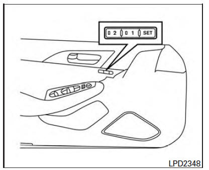
3. Push the SET switch and, within 5 seconds, push the memory switch (1 or 2).
4. The indicator light for the pushed memory switch will come on and stay on for approximately 5 seconds.
5. The chime will sound if the memory has been stored.
NOTE:
If a NEW memory position is stored in the same memory switch, the previous memory position will be overwritten by the new stored position.
Confirming memory storage
Push the SET switch.
- If a memory position has not been stored in the switch (1 or 2) the indicator light for the respective switch will come on for approximately 0.5 seconds.
- If a memory position has been stored in the switch (1 or 2) then the indicator light for the respective switch will stay on for approximately 5 seconds.
Linking an Intelligent Key to the meter display (if so equipped)
Each Intelligent Key, up to a maximum of four, can be linked to the meter display.
1. When the system is enabled, the recognized Intelligent Key is displayed at start up, as well as within "Key-Linked Settings".
2. When the system is active, the meter setting items are memorized for each Intelligent Key that has been enabled in the system.
3. The auto drive positioner system is memorized automatically when the ignition switch is turned from ON to OFF by the Intelligent Key with no need to set separate buttons for recalling and memorizing positions.
4. If two Intelligent Keys are in the vehicle, the system will recognize the Intelligent Key that was used most recently, such as to unlock/lock the door.
5. If there is a desire to change to another Intelligent Key while in the vehicle, the user must turn the ignition OFF and initiate communication from the desired Intelligent Key.
a. Ignition from ON position to the OFF
b. Unlock door with the desired Intelligent Key
c. The desired Intelligent Key number should appear on the meter display.
 Memory Storage Function (Key-Link)
Use the following process to setup key-link:
1. Unlock the vehicle with the desired Intelligent
Key while the ignition is OFF.
2. Place the ignition in the ON position.
3. Within the "Sett ...
 Entry/exit function
This system is designed so that the driver's seat
and automatic operation steering column will automatically
move when the shift lever is in the P
(Park) position. This allows the driver to get int ...
Other materials:
P0826 up and down shift SW
Description
Manual mode switch transmits signals (manual mode, not manual mode, shift up
and shift down) to combination
meter.
Paddle shifter transmits signals (shift up and shift down) to combination
meter. (With paddle shifter)
Combination meter transmits signals (manual mode, not manual ...
Headlamp aiming adjustment
Description
PREPARATION BEFORE ADJUSTING
CAUTION: Do not use organic solvent
(thinner, gasoline etc.).
NOTE:
For details, refer to the regulations in your own country.
Perform aiming adjustment if the vehicle front body has been
repaired and/or the headlamp assembly has been replaced.
...
U121D AV control unit
DTC Logic
Diagnosis Procedure
1.CHECK PLAYBACK OF A DISK (CD)
U121E AV CONTROL UNIT
DTC Logic
Diagnosis Procedure
1.CHECK PLAYBACK OF A DISK (CD)
U1225 AV CONTROL UNIT
DTC Logic
DTC DETECTION LOGIC
U1227 AV CONTROL UNIT
DTC Logic
Diagnosis Procedure
1.CHECK PLAYBACK OF A ...
Nissan Maxima Owners Manual
- Illustrated table of contents
- Safety-Seats, seat belts and supplemental restraint system
- Instruments and controls
- Pre-driving checks and adjustments
- Monitor, climate, audio, phone and voice recognition systems
- Starting and driving
- In case of emergency
- Appearance and care
- Do-it-yourself
- Maintenance and schedules
- Technical and consumer information
Nissan Maxima Service and Repair Manual

0.0073