Nissan Maxima Service and Repair Manual: B2615 front blower motor relay circuit
Description
BCM controls the various electrical components and simultaneously supplies power according to the power supply position.
BCM checks the power supply position internally.
DTC Logic
DTC DETECTION LOGIC
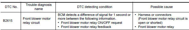
DTC CONFIRMATION PROCEDURE
1. PERFORM DTC CONFIRMATION PROCEDURE
- Turn ignition switch ON under the following conditions, and wait for at least 1 second.
- CVT selector lever is in the P or N position.
- Release brake pedal.
- Check "Self diagnostic result" with CONSULT.
Diagnosis Procedure
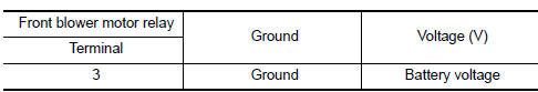
1.CHECK FRONT BLOWER MOTOR RELAY POWER SUPPLY
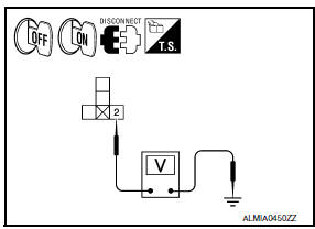
- Turn ignition switch OFF.
- Disconnect front blower motor relay.
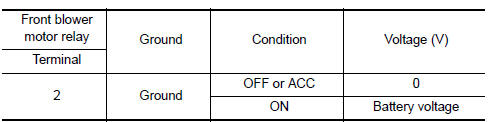
- Check voltage between front blower motor relay harness connector and ground under the following conditions.
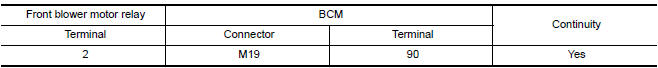
2. CHECK FRONT BLOWER MOTOR RELAY POWER SUPPLY CIRCUIT
- Turn ignition switch OFF.
- Disconnect BCM harness connector.
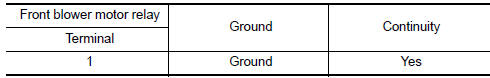
- Check continuity between front blower motor relay harness connector and BCM harness connector.
- Check continuity between front blower motor relay harness connector and ground.
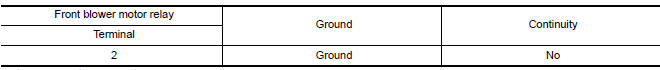
3. CHECK FRONT BLOWER MOTOR RELAY GROUND CIRCUIT
- Turn ignition switch OFF.
- Check continuity between front blower motor relay harness connector and ground.
4.CHECK FRONT BLOWER MOTOR RELAY POWER SUPPLY CIRCUIT-2
Check voltage between front blower motor relay harness connector and ground.
5. CHECK FRONT BLOWER MOTOR RELAY
6. CHECK INTERMITTENT INCIDENT
Component Inspection (Front Blower Motor Relay)
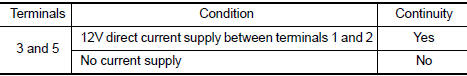
1.CHECK FRONT BLOWER MOTOR RELAY
- Turn ignition switch OFF.
- Remove front blower motor relay.
- Check the continuity between front blower motor relay terminals under the following conditions.
 B2614 ACC relay circuit
Description
BCM controls the various electrical components and simultaneously supplies
power according to the power
supply position.
BCM checks the power supply position internally.
DTC Logic ...
 B2616 ignition relay circuit
Description
BCM controls the various electrical components and simultaneously supplies
power according to the power
supply position.
BCM checks the power supply position internally.
DTC Logic ...
Other materials:
Precaution
PRECAUTIONS
Precaution for Supplemental Restraint System (SRS) "AIR BAG" and
"SEAT BELT PRE-TENSIONER"
The Supplemental Restraint System such as "AIR BAG" and "SEAT BELT
PRE-TENSIONER", used along with a front seat belt, helps to reduce the risk
or severity of injury to the driver and front ...
Water pump
Exploded View
Water pump
O-rings
Timing chain tensioner
Intake valve timing control solenoid
valve cover (RH) (bank 1)
Water pump cover
Removal and Installation
WARNING:
Do not remove the radiator cap when the engine is hot. Serious burns could occur
from high pressure
co ...
Nissan Maxima Owners Manual
- Illustrated table of contents
- Safety-Seats, seat belts and supplemental restraint system
- Instruments and controls
- Pre-driving checks and adjustments
- Monitor, climate, audio, phone and voice recognition systems
- Starting and driving
- In case of emergency
- Appearance and care
- Do-it-yourself
- Maintenance and schedules
- Technical and consumer information
Nissan Maxima Service and Repair Manual

0.0075