Nissan Maxima Service and Repair Manual: B2616 ignition relay circuit
Description
BCM controls the various electrical components and simultaneously supplies power according to the power supply position.
BCM checks the power supply position internally.
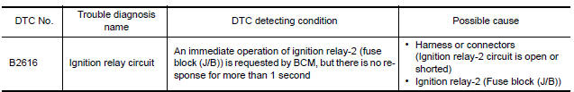
DTC Logic
DTC DETECTION LOGIC
DTC CONFIRMATION PROCEDURE
1. PERFORM DTC CONFIRMATION PROCEDURE
- Turn ignition switch ON under the following conditions, and wait for at least 1 second.
- CVT selector lever is in the P or N position
- Release brake pedal
- Check "Self diagnostic result" with CONSULT.
Diagnosis Procedure
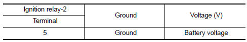
1. CHECK IGNITION RELAY-2 POWER SUPPLY
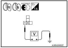
- Turn ignition switch OFF.
- Disconnect ignition relay-2.
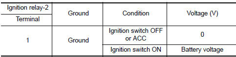
- Check voltage between ignition relay-2 harness connector and ground under the following conditions.
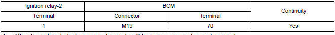
2. CHECK IGNITION RELAY-2 POWER SUPPLY CIRCUIT-1
- Turn ignition switch OFF.
- Disconnect BCM harness connector.
- Check continuity between ignition relay-2 harness connector and BCM harness connector.
- Check continuity between ignition relay-2 harness connector and ground.
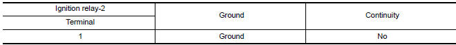
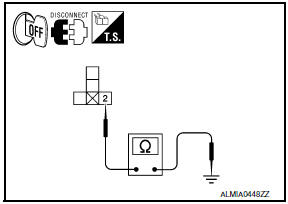
3. CHECK IGNITION RELAY-2 GROUND CIRCUIT
- Turn ignition switch OFF.
- Check continuity between ignition relay-2 harness connector and ground.
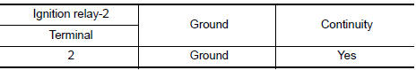
4. CHECK IGNITION RELAY-2 POWER SUPPLY CIRCUIT-2
Check voltage between ignition relay-2 harness connector and ground
5. CHECK IGNITION RELAY-2
6. CHECK INTERMITTENT INCIDENT
Component Inspection (Ignition Relay-2)
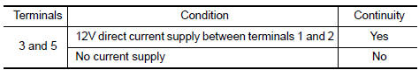
1. CHECK IGNITION RELAY-2
- Turn ignition switch OFF.
- Remove ignition relay-2.
- Check the continuity between ignition relay-2 terminals under the following conditions.
 B2615 front blower motor relay circuit
Description
BCM controls the various electrical components and simultaneously supplies
power according to the power
supply position.
BCM checks the power supply position internally.
DTC Logic ...
 B2618 BCM
Description
BCM controls the various electrical components and simultaneously supplies
power according to the power
supply position.
BCM checks the power supply position internally.
DTC Logic ...
Other materials:
Seat belts
The seat belts can be cleaned by wiping them
with a sponge dampened in a mild soap solution.
Allow the belts to dry completely in the shade
before using them. For additional information,
refer to "Seat belt maintenance" in the "Safety-
-Seats, seat belts and supplemental restraint
system" se ...
Front door speaker
Description
The audio unit sends audio signals to the BOSE speaker amp. The BOSE speaker
amp. amplifies the audio signals before sending them to the front door
speakers using the audio signal circuits.
Diagnosis Procedure
1.CONNECTOR CHECK
Check the audio unit, BOSE speaker amp. and speaker ...
RGB (G: green) signal circuit
Description
Transmit the image displayed with AV control unit with RGB signal to the
display unit.
Diagnosis Procedure
1.CHECK CONTINUITY RGB (G: GREEN) SIGNAL CIRCUIT
Turn ignition switch OFF.
Disconnect display unit connector M141 and AV control unit
connector M117.
Check conti ...
Nissan Maxima Owners Manual
- Illustrated table of contents
- Safety-Seats, seat belts and supplemental restraint system
- Instruments and controls
- Pre-driving checks and adjustments
- Monitor, climate, audio, phone and voice recognition systems
- Starting and driving
- In case of emergency
- Appearance and care
- Do-it-yourself
- Maintenance and schedules
- Technical and consumer information
Nissan Maxima Service and Repair Manual

0.0056