Nissan Maxima Service and Repair Manual: Shift lock system
System Diagram
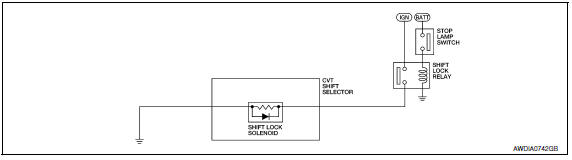
System Description
The selector lever cannot be shifted from "P" position to any other position unless the ignition switch is in the ON position and the brake pedal is depressed.
Component Parts Location
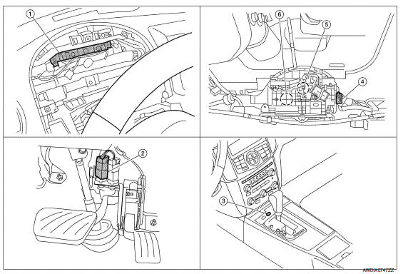
- BCM (view with combination meter removed)
- Stop lamp switch
- Shift lock release
- CVT shift selector connector
- Park position switch 6. Shift lock solenoid
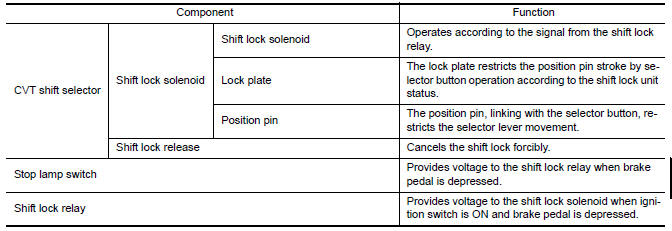
Component Description
 Shift control system
System Diagram
NOTE: The gear ratio is set for each position separately.
System Description
In order to select the gear ratio that can obtain the driving force in
accordance with driver's inten ...
 On board diagnostic (OBD) system
Diagnosis Description
DESCRIPTION
The CVT system has two self-diagnostic systems.
The first is the emission-related on board diagnostic system (OBD-II) performed
by the TCM in combination
wit ...
Other materials:
Main line between HVAC and A-bag circuit
Diagnosis Procedure
1.CHECK HARNESS CONTINUITY (OPEN CIRCUIT)
Turn the ignition switch OFF.
Disconnect the battery cable from the negative
terminal.
Disconnect the following harness connectors.
A/C auto amp.
Harness connectors M1 and ...
Headlights
Replacing the halogen headlight bulb
(if so equipped)
The headlight is a semi-sealed beam type which
uses a replaceable headlight (halogen) bulb.
They can be replaced from inside the engine
compartment without removing the headlight assembly.
If headlight bulb replacement is required, it i ...
Power consumption control system
System Diagram
System Description
OUTLINE
BCM incorporates a power saving control function that reduces the
power consumption according to the
vehicle status.
BCM switches the status (control mode) by itself with the power
saving control function. It performs the sleep
reques ...
Nissan Maxima Owners Manual
- Illustrated table of contents
- Safety-Seats, seat belts and supplemental restraint system
- Instruments and controls
- Pre-driving checks and adjustments
- Monitor, climate, audio, phone and voice recognition systems
- Starting and driving
- In case of emergency
- Appearance and care
- Do-it-yourself
- Maintenance and schedules
- Technical and consumer information
Nissan Maxima Service and Repair Manual

0.0059