Nissan Maxima Service and Repair Manual: P0171, P0174 fuel injection system function
DTC Logic
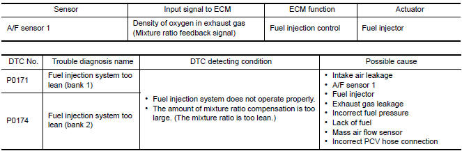
DTC DETECTION LOGIC
With the Air/Fuel Mixture Ratio Self-Learning Control, the actual mixture ratio can be brought closely to the theoretical mixture ratio based on the mixture ratio feedback signal from A/F sensor 1. The ECM calculates the necessary compensation to correct the offset between the actual and the theoretical ratios.
In case the amount of the compensation value is extremely large (the actual mixture ratio is too lean), the ECM judges the condition as the fuel injection system malfunction and illuminates the MIL (2 trip detection logic).
DTC CONFIRMATION PROCEDURE
1.PRECONDITIONING
If DTC Confirmation Procedure has been previously conducted, always perform the following before conducting the next test.
- Turn ignition switch OFF and wait at least 10 seconds.
- Turn ignition switch ON.
- Turn ignition switch OFF and wait at least 10 seconds
2.PERFORM DTC CONFIRMATION PROCEDURE-I
- Clear the mixture ratio self-learning value. Refer to EC-24, "MIXTURE RATIO SELF-LEARNING VALUE CLEAR : Special Repair Requirement".
- Start engine.
3.RESTART ENGINE
If it is difficult to start engine, the fuel injection system has a malfunction, too.
Crank engine while depressing accelerator pedal.
NOTE:
- When depressing accelerator pedal three-fourths (3/4) or more, the control system does not start the engine. Do not depress accelerator pedal too much.
4.PERFORM DTC CONFIRMATION PROCEDURE-II
- Keep engine idle for at least 5 minutes.
- Check 1st trip DTC.
5.PERFORM DTC CONFIRMATION PROCEDURE-III
- Turn ignition switch OFF and wait at least 10 seconds.
- Start engine.
- Maintain the following conditions for at least 10 consecutive
minutes.
Hold the accelerator pedal as steady as possible. CAUTION: Always drive vehicle at a safe speed.
- Check 1st trip DTC.

Diagnosis Procedure
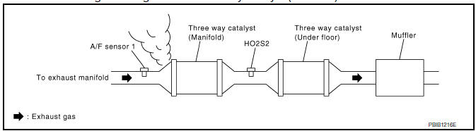
1.CHECK EXHAUST GAS LEAKAGE
- Start engine and run it at idle.
- Listen for an exhaust gas leakage before three way catalyst (manifold).
2.CHECK FOR INTAKE AIR LEAKAGE
- Listen for an intake air leakage after the mass air flow sensor.
- Check PCV hose connection.
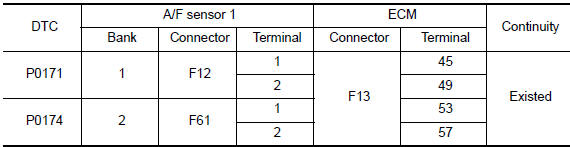
3.CHECK A/F SENSOR 1 INPUT SIGNAL CIRCUIT
- Turn ignition switch OFF.
- Disconnect corresponding A/F sensor 1 harness connector.
- Disconnect ECM harness connector.
- Check the continuity between A/F sensor 1 harness connector and ECM harness connector.
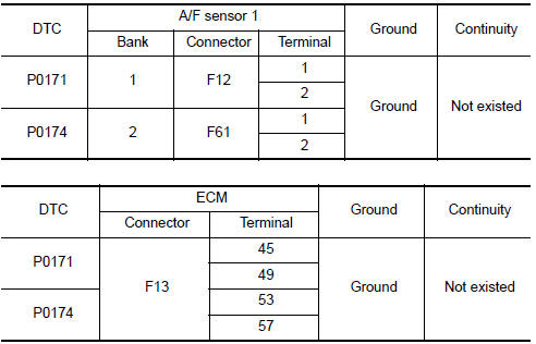
- Check the continuity between A/F sensor 1 harness connector and ground, or ECM harness connector and ground.
- Also check harness for short to power.
4.CHECK FUEL PRESSURE
- Release fuel pressure to zero. Refer to EC-592, "Inspection".
- Install fuel pressure gauge kit [SST (J-44321)] and check fuel pressure.
At idling: Approximately 350 kPa (3.57 kg/cm2, 51 psi)
5. DETECT MALFUNCTIONING PART
Check fuel hoses and fuel tubes for clogging.
6.CHECK MASS AIR FLOW SENSOR
- With CONSULT Install all removed parts.
- Check "MASS AIR FLOW" in "DATA MONITOR" mode with CONSULT.
For specification, refer to EC-596, "Mass Air Flow Sensor".
With GST
- Install all removed parts.
- Check mass air flow sensor signal in Service $01 with GST.
7.CHECK FUNCTION OF FUEL INJECTOR
With CONSULT
- Start engine.
- Perform "POWER BALANCE" in "ACTIVE TEST" mode with CONSULT.
- Check that each circuit produces a momentary engine speed drop.
With GST
- Let engine idle.
- Listen to each fuel injector operating sound.
8.CHECK FUEL INJECTOR
- Turn ignition switch OFF.
- Confirm that the engine is cooled down and there are no fire hazards near the vehicle.
- Disconnect all fuel injector harness connectors.
- Remove fuel tube assembly. Refer to EM-43, "Removal and
Installation".
Keep fuel hose and all fuel injectors connected to fuel tube.
- For DTC P0171, reconnect fuel injector harness connectors on bank
1.
For DTC P0174, reconnect fuel injector harness connectors on bank 2.
- Disconnect all ignition coil harness connectors.
- Prepare pans or saucers under each fuel injector.
- Crank engine for about 3 seconds.
For DTC P0171, check that fuel sprays out from fuel injectors on bank 1.
For DTC P0174, check that fuel sprays out from fuel injectors on bank 2.
Fuel should be sprayed evenly for each fuel injector.
9.CHECK INTERMITTENT INCIDENT
 P014C, P014D, P014E, P014F, P015A, P015B, P015C, P015D A/F sensor
1
P014C, P014D, P014E, P014F, P015A, P015B, P015C, P015D A/F sensor
1
Description
The air fuel ratio (A/F) sensor 1 is a planar one-cell limit current sensor.
The sensor element of the A/F sensor 1 is composed an electrode
layer, which transports ions. It has ...
 P0172, P0175 fuel injection system function
DTC Logic
DTC DETECTION LOGIC
With the Air/Fuel Mixture Ratio Self-Learning Control, the actual mixture
ratio can be brought closely to the
theoretical mixture ratio based on the mixture ratio f ...
Other materials:
Basic inspection
DIAGNOSIS AND REPAIR WORKFLOW
Work Flow
OVERALL SEQUENCE
DETAILED FLOW
1.INTERVIEW FOR MALFUNCTION
Find out what the customer's concerns are.
2.SYMPTOM CHECK
Verify the symptom from the customer's information.
3.BASIC INSPECTION
Check the operation of each part. Check if any concerns occu ...
Memory Storage Function (Key-Link)
Use the following process to setup key-link:
1. Unlock the vehicle with the desired Intelligent
Key while the ignition is OFF.
2. Place the ignition in the ON position.
3. Within the "Settings" menu of the vehicle
information display, select "Key-Linked Settings"
and press the OK butto ...
Automatic drive positioner (if so equipped)
The automatic drive positioner system has three
features:
Memory storage function (Key-link)
Memory storage function (Switch)
Entry/exit function
Key-link, when enabled, automatically retains the
driver's last seat, automatic steering wheel, and
outside mirror positions for that specif ...
Nissan Maxima Owners Manual
- Illustrated table of contents
- Safety-Seats, seat belts and supplemental restraint system
- Instruments and controls
- Pre-driving checks and adjustments
- Monitor, climate, audio, phone and voice recognition systems
- Starting and driving
- In case of emergency
- Appearance and care
- Do-it-yourself
- Maintenance and schedules
- Technical and consumer information
Nissan Maxima Service and Repair Manual

0.0066