Nissan Maxima Service and Repair Manual: P014C, P014D, P014E, P014F, P015A, P015B, P015C, P015D A/F sensor 1
Description
The air fuel ratio (A/F) sensor 1 is a planar one-cell limit current sensor.
The sensor element of the A/F sensor 1 is composed an electrode layer, which transports ions. It has a heater in the element.
The sensor is capable of precise measurement = 1, but also in the lean and rich range. Together with its control electronics, the sensor outputs a clear, continuous signal throughout a wide range.
The exhaust gas components diffuse via the diffusion layer at the sensor cell. An electrode layer is applied voltage, and this current relative oxygen density in lean. Also this current relative hydrocarbon density in rich.
Therefore, the A/F sensor 1 is able to indicate air fuel ratio by this electrode layer of current. In addition, a heater is integrated in the sensor to ensure the required operating temperature of about 800C (1,472F).
DTC Logic
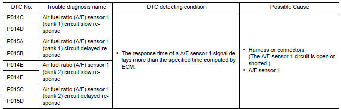
DTC DETECTION LOGIC
To judge malfunctions, this diagnosis measures response time of the A/F signal computed by ECM from the A/ F sensor 1 signal. The time is compensated by engine operating (speed and load), fuel feedback control constant, and the A/F sensor 1 temperature index. Judgment is based on whether the compensated time (the A/F signal cycling time index) is inordinately long or not.
DTC CONFIRMATION PROCEDURE
1.PRECONDITIONING
If DTC Confirmation Procedure has been previously conducted, always perform the following procedure before conducting the next test.
- Turn ignition switch OFF and wait at least 10 seconds.
- Turn ignition switch ON.
- Turn ignition switch OFF and wait at least 10 seconds.
TESTING CONDITION: Before performing the following procedure, confirm that battery voltage is more than 11 V at idle.
2.PERFORM DTC CONFIRMATION PROCEDURE-1
With CONSULT
- Start engine and warm it up to normal operating temperature.
- Turn ignition switch OFF and wait at least 10 seconds.
- Turn ignition switch ON.
- Turn ignition switch OFF and wait at least 10 seconds.
- Start engine and keep the engine speed between 3,500 and 4,000 rpm for at least 1minute under no load.
- Let engine idle for 1 minute.
- Increase the engine speed up to about 3,600 rpm and keep it for 10 seconds.
- Fully release accelerator pedal and then let engine idle for about 1 minute.
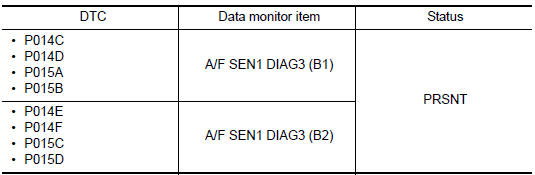
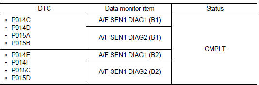
- Check the items status of "DATA MONITOR" as follows.
NOTE: If "PRSNT" changed to "ABSNT"
3.PERFORM DTC CONFIRMATION PROCEDURE-2
With CONSULT
Perform DTC confirmation procedure-1 again.
4.PERFORM DTC CONFIRMATION PROCEDURE-2
With CONSULT
- Wait for about 20 seconds at idle.
- Check the items status of "DATA MONITOR" as follows.
NOTE: If "CMPLT" changed to "INCMP"
5.PERFORM SELF-DIAGNOSIS
With CONSULT
Check the "SELF-DIAG RESULT".
6.CHECK AIR-FUEL RATIO SELF-LEARNING VALUE
With GST
- Start engine and warm it up to normal operating temperature.
- Select Service $01 with GST.
- Calculate the total value of "Short term fuel trim" and "Long term fuel trim" indications.
7.DETECT MALFUNCTIONING PART
Check the following.
- Intake air leaks
- Exhaust gas leaks
- Incorrect fuel pressure
- Lack of fuel
- Fuel injector
- Incorrect PCV hose connection
- PCV valve
- Mass air flow ensor
8.PERFORM DTC CONFIRMATION PROCEDURE
- Turn ignition switch OFF and wait at least 10 seconds.
- Turn ignition switch ON.
- Turn ignition switch OFF and wait at least 10 seconds.
- Start engine and keep the engine speed between 3,500 and 4,000 rpm for at least 1 minute under no load.
- Let engine idle for 1 minute.
- Increase the engine speed up to about 3,600 rpm and keep it for 10 seconds.
- Fully release accelerator pedal and then let engine idle for about 1 minute.
- Check 1st trip DTC.
Diagnosis Procedure
1.RETIGHTEN A/F SENSOR 1
Loosen and retighten the A/F sensor 1.
2.CHECK EXHAUST GAS LEAKAGE
1. Start engine and run it at idle.
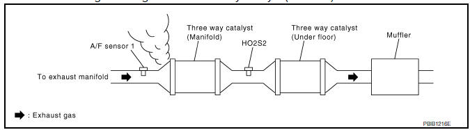
Listen for an exhaust gas leakage before three way catalyst (manifold).
3.CHECK FOR INTAKE AIR LEAK
Listen for an intake air leak after the mass air flow sensor.
4.CLEAR THE MIXTURE RATIO SELF-LEARNING VALUE
- Clear the mixture ratio self-learning value. Refer to EC-24, "MIXTURE RATIO SELF-LEARNING VALUE CLEAR : Special Repair Requirement".
- Run engine for at least 10 minutes at idle speed.
5.CHECK AIR FUEL RATIO (A/F) SENSOR 1 POWER SUPPLY
- Disconnect A/F sensor 1 harness connector.
- Turn ignition switch ON.
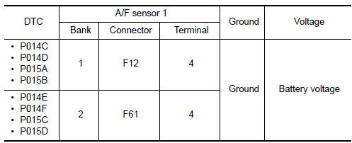
- Check the voltage between A/F sensor 1 harness connector and ground.
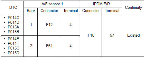
6.CHECK AIR FUEL RATIO (A/F) SENSOR 1 POWER SUPPLY CIRCUIT
- Turn ignition switch OFF.
- Disconnect IPDM E/R harness connector.
- Check the continuity between A/F sensor 1 harness connector and IPDM E/R harness connector.
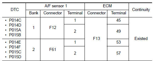
7.CHECK A/F SENSOR 1 INPUT SIGNAL CIRCUIT FOR OPEN AND SHORT
- Turn ignition switch OFF.
- Disconnect ECM harness connector.
- Check the continuity between A/F sensor 1 harness connector and ECM harness connector.
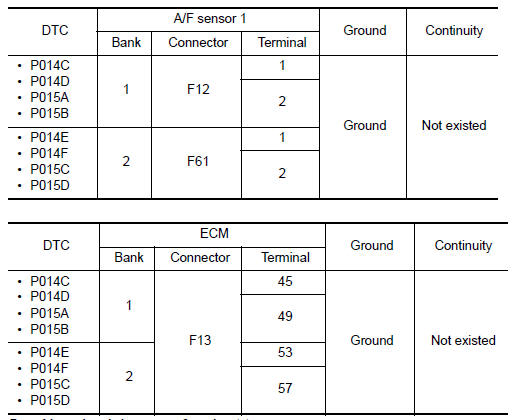
- Check the continuity between A/F sensor 1 harness connector and ground, or ECM harness connector and ground.
- Also check harness for short to power.
8.CHECK AIR FUEL RATIO (A/F) SENSOR 1 HEATER
Check air fuel ratio (A/F) sensor 1 heater.
9.CHECK MASS AIR FLOW SENSOR
Check both mass air flow sensor (bank 1 and bank 2).
10.CHECK PCV VALVE
Check PCV valve
11.CHECK INTERMITTENT INCIDENT
Check intermittent incident.
 P0139, P0159 HO2S2
Description
The heated oxygen sensor 2, after three way catalyst (manifold),
monitors the oxygen level in the exhaust gas on each bank.
Even if switching characteristics of the air fuel rati ...
 P0171, P0174 fuel injection system function
DTC Logic
DTC DETECTION LOGIC
With the Air/Fuel Mixture Ratio Self-Learning Control, the actual mixture
ratio can be brought closely to the
theoretical mixture ratio based on the mixture ratio f ...
Other materials:
Precaution
Precaution for Supplemental Restraint System (SRS) "AIR BAG" and
"SEAT BELT PRE-TENSIONER"
The Supplemental Restraint System such as "AIR BAG" and "SEAT BELT
PRE-TENSIONER", used along with a front seat belt, helps to reduce the risk
or severity of injury to the driver and front passenger for ...
ECU diagnosis information
TCM
Reference Value
VALUES ON THE DIAGNOSIS TOOL
TERMINAL LAYOUT
PHYSICAL VALUES
Fail-safe
The TCM has an electrical fail-safe mode. In this mode
TCM operates even if there is an error in a main electronic
control input/output signal circuit.
FAIL-SAFE FUNCTION
If any malf ...
Diagnosis and repair workflow
Work Flow
OVERALL SEQUENCE
DETAILED FLOW\
1.CHECK SYMPTOM
Check the malfunction symptoms by performing the following items.
Interview the customer to obtain the malfunction information
(conditions and environment when the malfunction occurred).
Check the symptom.
2.SELF-DIAGNOSIS ( ...
Nissan Maxima Owners Manual
- Illustrated table of contents
- Safety-Seats, seat belts and supplemental restraint system
- Instruments and controls
- Pre-driving checks and adjustments
- Monitor, climate, audio, phone and voice recognition systems
- Starting and driving
- In case of emergency
- Appearance and care
- Do-it-yourself
- Maintenance and schedules
- Technical and consumer information
Nissan Maxima Service and Repair Manual

0.008