Nissan Maxima Service and Repair Manual: Oil pump
Removal and Installation
REMOVAL
- Remove the engine from the vehicle. Refer to EM-103, "Removal and Installation".
- Remove the upper oil pan. Refer to EM-37, "Removal and Installation (Upper Oil Pan)".
- Remove the timing chain. Refer to EM-64, "Removal and Installation".
- Remove oil pump assembly.
INSTALLATION
Installation is in the reverse order of removal.
Disassembly and Assembly
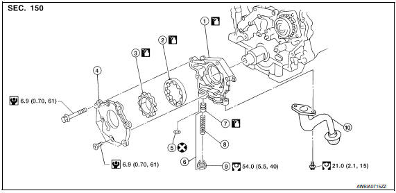
- Oil pump housing
- Outer rotor
- Inner rotor
- Oil pump cover
- O-ring
- Regulator valve set
- Regulator valve
- Spring
- Regulator plug
- Oil strainer
CAUTION: Before assembly, apply new engine oil to the parts as shown.
DISASSEMBLY
- Remove the oil pump cover.
- Remove inner rotor and outer rotor from oil pump housing. CAUTION: The outer rotor has directional vanes in relation to the rotation of the oil pump shaft. Note the outer rotor vane direction for assembly.
- Remove oil strainer from oil pump housing.
- After removing regulator plug, remove spring and regulator valve.
INSPECTION AFTER DISASSEMBLY
Clearance of Oil Pump Parts
- Measure clearance with feeler gauge.
- Clearance between outer rotor and oil pump body (position 1).
- Tip clearance between inner rotor and outer rotor (position 2).
- Measure clearance with feeler gauge and straightedge.
- Side clearance between inner rotor and oil pump body (position 3).
- Side clearance between outer rotor and oil pump body (position 4).
- Calculate the clearance between inner rotor and oil pump body as follows:
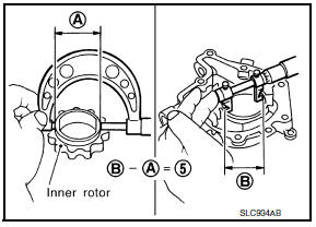
- Measure the outer diameter of protruded portion of inner rotor (position A).
- Measure the inner diameter of oil pump body with inside
micrometer (position B).
(clearance 5) = (inner diameter of oil pump body B) - (outer diameter of inner rotor A)
- If out of specifications, replace oil pump assembly.
Regulator Valve
- Visually inspect components for wear and damage.
- Check oil pressure regulator valve sliding surface and valve spring.
- Coat regulator valve with engine oil. Check that it falls smoothly
into the valve hole by its own weight.
If damaged, replace oil pump assembly.
Regulator Valve Clearance
(Clearance 6) = D (Valve hole diameter) - E (Outer diameter of valve)
If it exceeds the standard, replace the oil pump assembly.
CAUTION:
- Coat regulator valve with engine oil.
- Check that it falls smoothly into the valve hole by its own weight.
Assembly
Assembly is in the reverse order of disassembly.
- Assemble the outer rotor in the correct vane orientation to rotation as noted during disassembly and the inner rotor with the groove on the oil pump cover side.
CAUTION:
- Do not reuse O-ring.
- Before assembly apply new engine oil to the parts as specified.

 Oil cooler
Removal and Installation
Oil filter
Oil cooler bolt
Water pipe
Water hose
Oil cooler
O-ring
Oil pan
Water pipe
Relief valve
&nbs ...
Other materials:
Display unit
Reference Value
TERMINAL LAYOUT
PHYSICAL VALUES
...
Precautions
PRECAUTION
Precaution for Supplemental Restraint System (SRS) "AIR BAG" and
"SEAT BELT PRE-TENSIONER "
The Supplemental Restraint System such as "AIR BAG" and "SEAT BELT PRE-TENSIONER
",
used along
with a front seat belt, helps to reduce the risk or ...
Basic inspection
DIAGNOSIS AND REPAIR WORKFLOW
Work Flow
OVERALL SEQUENCE
DETAILED FLOW
1. GET INFORMATION FOR SYMPTOM
Get the detailed information from the customer about the symptom (the
condition and the environment when
the incident/malfunction occurred).
2. CHECK DTC
Check DTC for BCM and IPDM ...
Nissan Maxima Owners Manual
- Illustrated table of contents
- Safety-Seats, seat belts and supplemental restraint system
- Instruments and controls
- Pre-driving checks and adjustments
- Monitor, climate, audio, phone and voice recognition systems
- Starting and driving
- In case of emergency
- Appearance and care
- Do-it-yourself
- Maintenance and schedules
- Technical and consumer information
Nissan Maxima Service and Repair Manual

0.0056